
Ultrasound imaging system and method using non-linear post-beamforming filter

a nonlinear, filter technology, applied in the field of ultrasound imaging, can solve the problems of harmonic generation, nonlinear propagation of ultrasound wave energy in biological tissues, and limited specificity between contrast agents and tissu

Inactive Publication Date: 2005-10-04
RGT UNIV OF MINNESOTA
View PDF22 Cites 72 Cited by
  • Summary
  • Abstract
  • Description
  • Claims
  • Application Information

AI Technical Summary

Benefits of technology

[0025]The solution generally is provided as a matrix including elements representative of the coefficients for the at least one non-linear filter kernel. The coefficients may be further defined by performing a two-dimensional autocorrelation on the matrix. Yet further, Singular value decomposition may be used to determine dominant eigenmodes for the matrix. Yet further, one or more eigenmodes may be identified and removed.

Problems solved by technology

Propagation of ultrasound wave energy in biological tissues is known to be non-linear, giving rise to generation of harmonics.
However, since harmonic imaging still receives signal from tissue, the specificity between contrast agent and tissue is still limited.
However, this technique puts significant constraints on the transducer bandwidth, f0−B / 2 to 2f0+B.
Significant signal loss occurs since most transducers are not capable of supporting such a bandwidth.
However, such techniques and enhancements are not without their own limitations.
When relying on the use of multiple transmissions, movement of the imaged region results in undesirable degradation of the image produced by the ultrasound system.

Method used


Image

  • Ultrasound imaging system and method using non-linear post-beamforming filter
  • Ultrasound imaging system and method using non-linear post-beamforming filter
  • Ultrasound imaging system and method using non-linear post-beamforming filter

Examples


Embodiment Construction

[0034]The present invention shall be generally described with reference to FIGS. 1-2. Thereafter, various additional embodiments and examples of the present invention shall be described with reference to FIGS. 1-6.

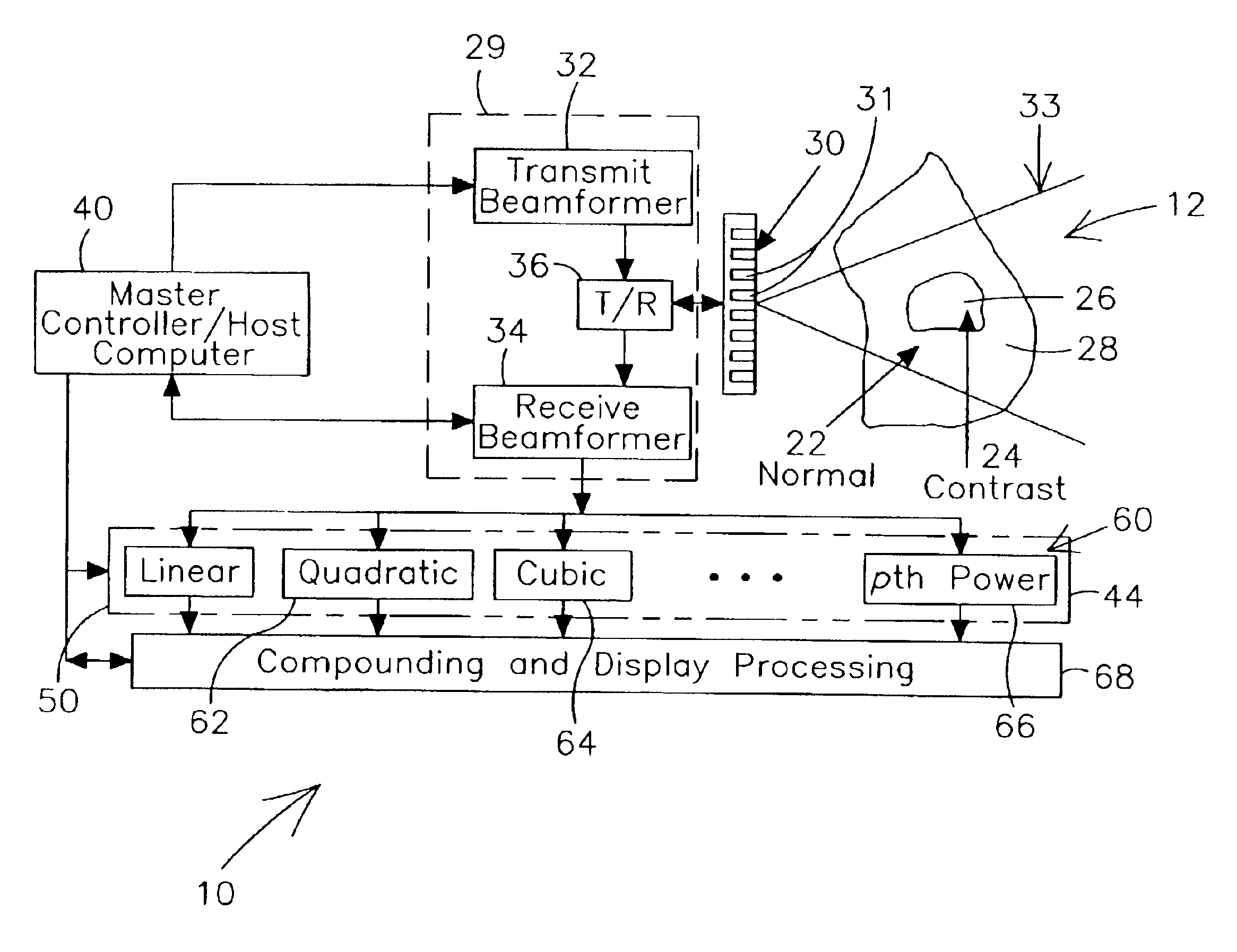
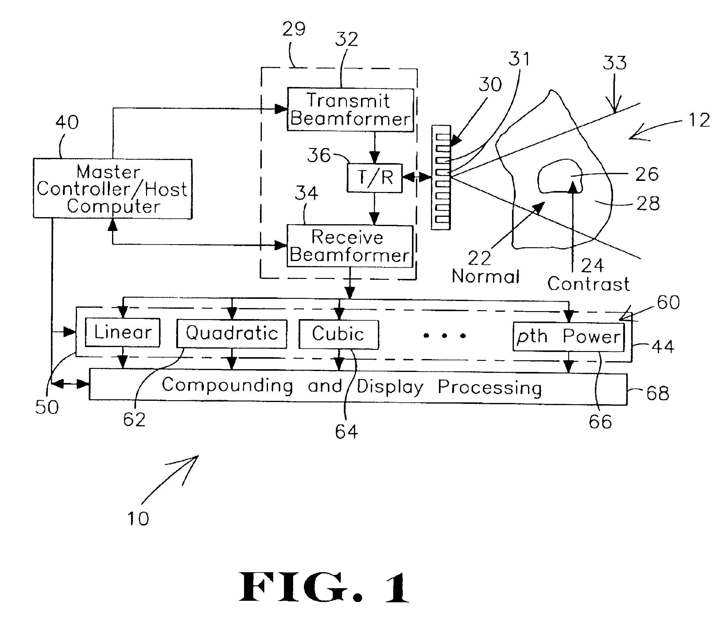
[0035]FIG. 1 shows an illustrative ultrasound imaging system 10 according to the present invention. The ultrasound imaging system 10 provides for an improvement in medical ultrasound imaging through the use of a dynamic non-linear post-beamforming filter represented generally by linear and non-linear kernels of filter bank 44. The non-linear post-beamforming filter is capable of separating the linear and non-linear components of image data, e.g., beamformed data representative of RF echo, returned from the region 12 being imaged by the ultrasound imaging system 10.

[0036]The imaging systems and filtering methods described herein are beneficial for use in various applications. In other words, various applications will benefit from the utilization of a dynamic non-linear post...


PUM


Abstract

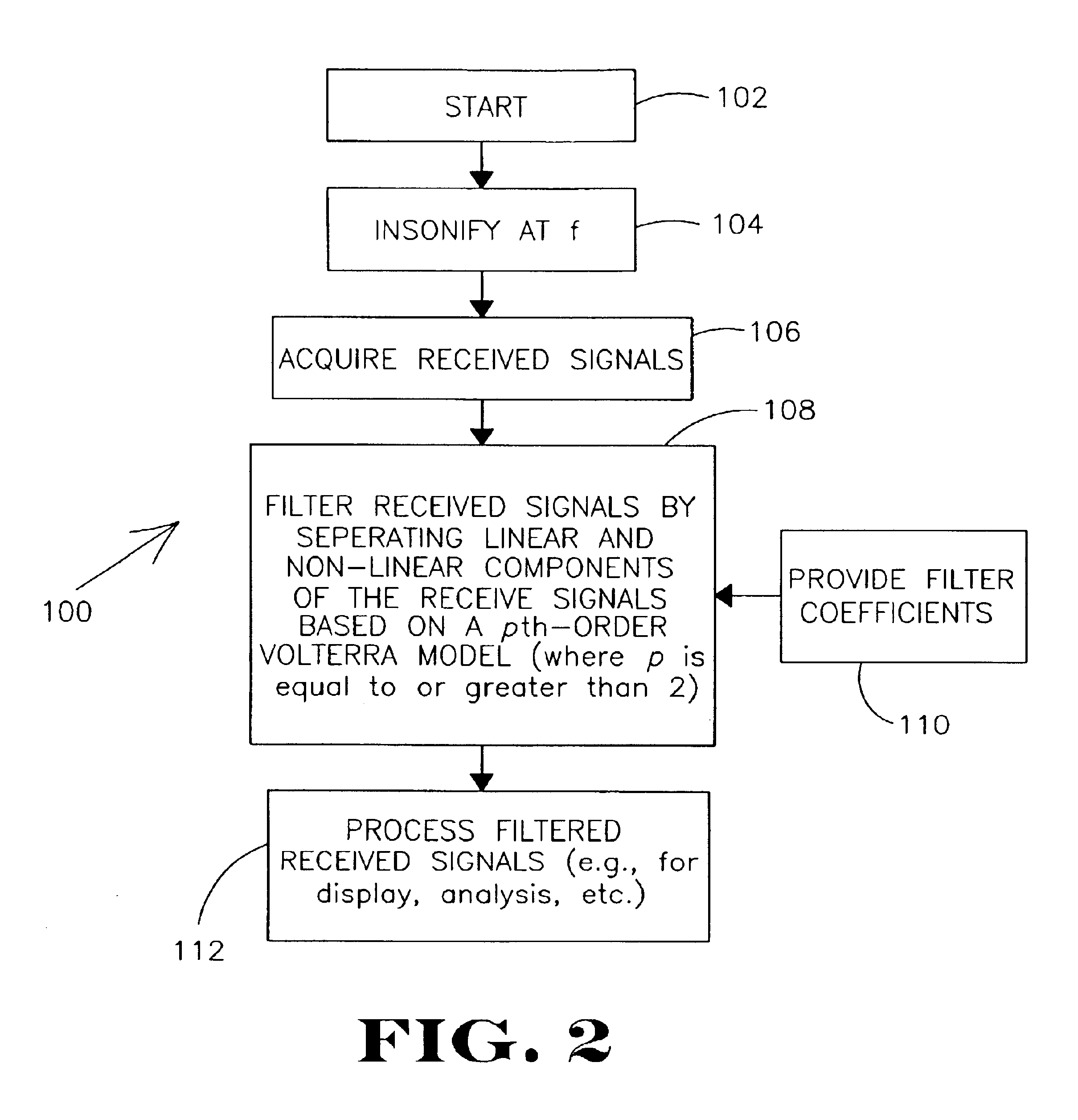
Systems and / or methods provide for ultrasound imaging through the use of a dynamic non-linear post-beamforming filter (e.g., based on a pth-order Volterra model) capable of separating the linear and non-linear components of image data. A coefficient identification algorithm for deriving coefficients for filter is also provided.

Description

CROSS REFERENCE TO RELATED APPLICATIONS[0001]This is a Continuation-in-Part of U.S. patent application Ser. No. 10 / 143,206 filed on 10 May 2002. now U.S. Pat. No. 6.705.993. entitled “ULTRASOUND IMAGING SYSTEM AND METHOD USING NON-LINEAR POST-BEAMFORMING FILTER”, which is hereby incorporated by reference.STATEMENT OF GOVERNMENT RIGHTS[0002]The present invention was made with support from the National Institute of Health (NIH) under Grant No, CA 66602 and Department of Defense (DoD)—Army Grant No. DAMD17-01-1-0330. The government may have certain rights in this invention.FIELD OF THE INVENTION[0003]The present invention relates generally to imaging. More particularly, the present invention pertains to the use of a non-linear post-beamforming filter in ultrasound imaging.BACKGROUND OF THE INVENTION[0004]Many conventional ultrasound scanners create two-dimensional images of tissue located in a region of interest in which brightness of a pixel in the image is based on intensity of echo ...

Claims


Application Information

Patent Timeline
Patent Type & Authority Patents(United States)
IPC IPC(8): G01S7/52
CPCG01S7/52038G01S7/52039
Inventor EBBINI, EMAD S.PHUKPATTARANONT, PORNCHAI
Owner RGT UNIV OF MINNESOTA
Learn More