Marking device and method for indicating locations on a support structure for fastener placement and measurement

a technology of fastener placement and positioning, which is applied in the direction of instruments, domestic mirrors, picture frames, etc., can solve the problems of unable to view the marking device, and not being able to provide the required force to the marking device, etc., to achieve the effect of quick and stable mounting of the articl

Inactive Publication Date: 2005-10-11
MUCHNIK BORIS A
View PDF46 Cites 70 Cited by
  • Summary
  • Abstract
  • Description
  • Claims
  • Application Information

AI Technical Summary

Benefits of technology

[0019]Yet another object of the present invention is to enable a user to simply and affordably suspend an article on a support surface via two article suspension points, thereby obviating the need for utilizing a suspension wire or cord.
[0020]Still another obj

Problems solved by technology

In particular, the recessed marking member devices are not suitable to accomplish marking for “blind spots”.
However, article mounting hardware to engage the fasteners are generally placed on the back of the article and are not visible during alignment with the supporting surface.
If the marking device is disposed in this fashion, a user is unable to view the marking device and consequently cannot provide the required force to that device to place a mark on the surface.
Further, the exposed marking member devices provide no protection from the marking member.
Thus, these devices enable the marking member to damage and/or mark the supporting surface at erroneous or inappropriate locations.
Moreover, the exposed marking member devices enable the marking member to contact a user, thereby providing a safety hazard for the user when the marking member is implemented by a sharp object (e.g., nail, punch, etc.).
In addition, marking with respect to blind spots becomes quite cumbersome.
However, since a

Method used


Image

  • Marking device and method for indicating locations on a support structure for fastener placement and measurement
  • Marking device and method for indicating locations on a support structure for fastener placement and measurement
  • Marking device and method for indicating locations on a support structure for fastener placement and measurement

Examples


Embodiment Construction

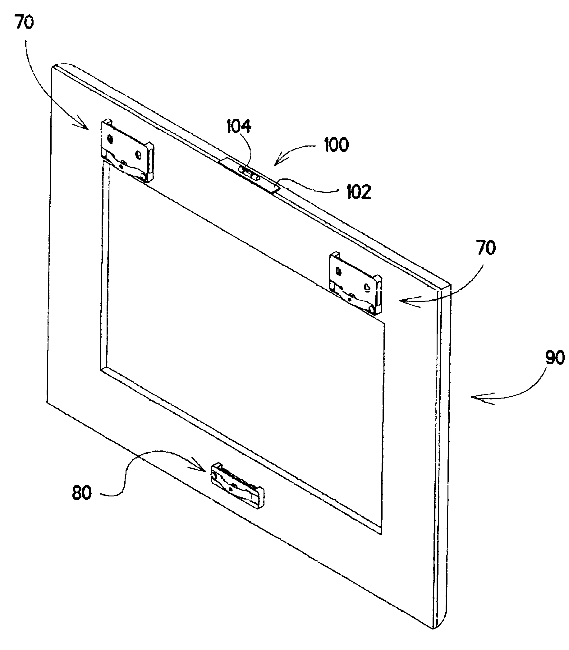
[0073]The present invention pertains to a marking device for marking a support surface or structure. The marking action of the device is generally a result of pressure applied somewhere to a device base and directed toward a surface to be marked. The force for initializing the action may be applied to the base in random areas (e.g., areas that are not restricted by the position of the device marking member). Thus, one or more marking devices may be removably secured to a measuring instrument or to an article, where the marking devices allow execution of a marking transfer action in response to force applied to areas of the instrument or article that are located some distance from the device marking member. The measuring instrument or article can be initially maneuvered along or over the surface to a desired location without providing any undesirable marks on the surface during the preparatory manipulations or initial positioning relative to the surface.

[0074]The marking device may f...


PUM


Abstract

A marking device of the present invention includes a resilient member to shield a marking member and enable an article with the device to traverse a surface without leaving a mark. The marking member is fixed to the device base and may have an adjustable height. The device may further include an indicator to provide a visual, audible or other type of signal indicating successful completion of marking. Further, the marking device may be slidably attached to measurement instruments to mark locations corresponding to desired measurements. In operation, the article or instrument with marking devices secured thereto is positioned at a desired location relative to the surface. Pressure is applied to the article or instrument, where marking members of the devices protrude through corresponding resilient members to produce marks on the surface. A level device with an adhesive base may be removably secured to an article for proper article orientation.

Description

BACKGROUND OF THE INVENTION[0001]1. Technical Field[0002]The present invention pertains to marking and measuring devices. In particular, the present invention pertains to a marking device that indicates locations on a support surface or structure for measurement purposes or for placement of fasteners to suspend or attach an article to that surface.[0003]2. Discussion of Related Art[0004]Marking devices are typically utilized to identify particular locations on a surface for performance of a task. For example, these devices may identify locations on a wall or other support surface for placement of fasteners to mount an article (e.g., picture frame, mirror, cornice, board, cabinet, shelf, etc.) on that support surface.[0005]One type of marking device disposes a marking member within a base to prevent contact with a surface during preparatory manipulations. Force is typically applied by the user directly to the proximal end of the marking device or member to urge the marking member fro...

Claims


Application Information

Patent Timeline
IPC IPC(8): A47G1/16A47G1/20B25H7/04B25H7/00
CPCA47G1/205B25H7/045
Inventor MUCHNIK, BORIS A.
Owner MUCHNIK BORIS A
Why Eureka
Try Eureka