Die casting machine

a technology of die casting machine and powder release agent, which is applied in the direction of manufacturing tools, foundry patterns, and moulding apparatus, etc., can solve the problems of insufficient performance of powder release agent, difficult to uniformly disperse powder release agent to the surface of the cavity, etc., and achieve the effect of stable quality die casting

Inactive Publication Date: 2005-10-11
TOSHIBA MASCH CO LTD
View PDF5 Cites 17 Cited by
  • Summary
  • Abstract
  • Description
  • Claims
  • Application Information

AI Technical Summary

Benefits of technology

[0011]An object of the present invention is to provide a die casting machine enabling the performances of a powder release agent and powder lubricant to be sufficiently exhibited when casting using a powder release agent or lubricant and enabling a stable quality die casting to be produced.

Problems solved by technology

With this coating method, however, depending on the shape of the cavity etc., it is difficult to cause the powder release agent to uniformly disperse to the surface of the cavity.
Unless the powder release agent is uniformly coated, the performance of the powder release agent cannot be sufficiently exhibited.

Method used


Image

  • Die casting machine
  • Die casting machine
  • Die casting machine

Examples


first embodiment

[0044

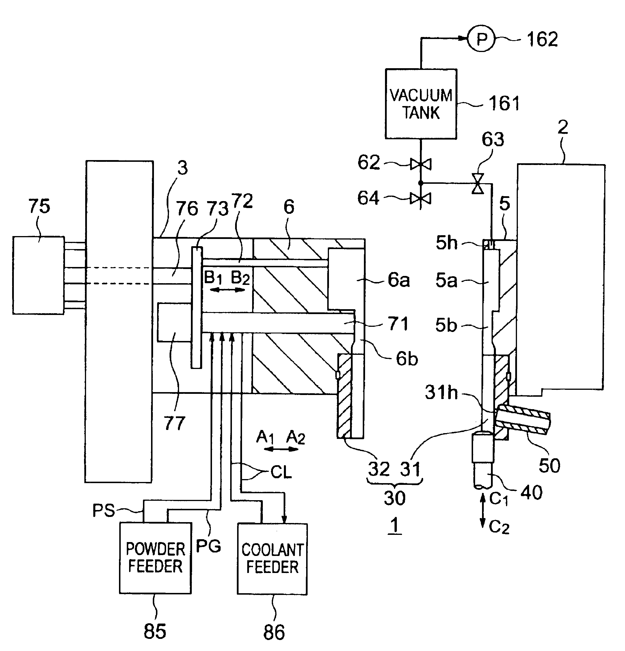
[0045]FIG. 1 is a view along the vertical direction showing the configuration of a die casting machine according to an embodiment of the present invention.

[0046]In FIG. 1, a die casting machine 1 is provided with affixed die 3 held at a fixed die plate 2, a movable die 6 held at a movable die plate 3, a sleeve 30 comprised of a split part 31 fixed to the fixed die 5 and a split part 32 fixed to the movable die 6, a plunger 40 fitting into the sleeve 30, a malt feed pipe 50 connected to the sleeve 30, a vacuum tank 161 connected to the fixed die 5, a plurality of ejecting pins 71, 72 provided on the to movable die 6, a powder feeder 85, and a coolant feeder 86. Note that the vacuum tank 161 is an embodiment of the evacuating means of the present invention, while the powder feeder 85 is an embodiment of the release agent feeding means and lubricant feeding means of the present invention.

[0047]The fixed die plate 2 is fixed on a not shown base. The movable die plate 3 is set on a ...

second embodiment

[0107

[0108]FIG. 11 is a sectional view along the vertical direction showing the configuration of principal parts of a die casting machine according to another embodiment of the present invention. Note that in FIG. 11, components the same as in the first embodiment are assigned the same reference numerals.

[0109]In FIG. 11, a die canting machine 101 is provided with a fixed die 5, a movable die 6, a sleeve 30 comprised of a split part 31 and a split part 32, a plunger 40, a melt feed pipe 50, a powder feeder 21, a vacuum tank 161, an electromagnetic pump 100 for feeding the sleeve 30 with molten metal ML through the melt feed pipe 50 connected to the split part 31 of the sleeve 30, and a metal melting and holding furnace 110 for holding the molten metal ML to be fed to the melt feed pipe 50.

[0110]Further, the die casting machine 101 has a check valve 70 provided between an evacuation path connecting the vacuum tank 161 and fixed die 5 and the outside of the die.

[0111]Further, the die ...


PUM

PropertyMeasurementUnit
circumferenceaaaaaaaaaa
pressureaaaaaaaaaa
frictionaaaaaaaaaa

Abstract

A die casting machine injecting and filling a molten metal into a cavity formed between a pair of dies so as to cast a product, comprising an ejecting pin for ejecting a casting by its front and sticking out inside the cavity and a powder feeder for feeding a powder release agent for promoting release of the casting from the dies, the ejecting pin including a release agent feed path for guiding powder release agent fed from the powder feeder to a front end of the ejecting pin and feeding it to the cavity.

Description

BACKGROUND OF THE INVENTION[0001]1. Field of the Invention[0002]The present invention relates to a die casting machine.[0003]2. Description of the Related Art[0004]A die casting machine is provided with a pair of dies, a fixed die plate and a movable die plate for holding these dies, a clamping unit for opening, closing, and clamping the dies, an injection apparatus provided with a plunger and sleeve for injecting and filling molten metal into a cavity formed between the dies, etc.[0005]In this due casting machine, to facilitate removal of the casting from the dies, the practice has been to coat a release agent on the inner surface of the cavity of the dies before casting. Further, to reduce the friction between the sleeve and plunger of the injection apparatus when injecting the molten metal into the cavity of the dies, the practice has been to coat a lubricant on the inner circumference of the sleeve before casting.[0006]As the release agent and lubricant, in the past frequent use...

Claims


Application Information

Patent Timeline
Patent Type & Authority Patents(United States)
IPC IPC(8): B22D17/22B22D17/20
CPCB22D17/2007B22D17/2236
Inventor SUZUKI, KAZUHIROKUBOTA, SHOKOTSURUDA, KAZUMIKUBOKI, ISAOTOYOSHIMA, TOSHIAKI
Owner TOSHIBA MASCH CO LTD
Why Eureka
Try Eureka