
Pressure assisted liquid supply assembly

a technology of liquid supply and assembly, which is applied in the direction of pliable tubular containers, instruments, and separation processes, etc., can solve the problems of operational or cleaning problems, the liquid column that feeds liquid into the spray gun can be lost, and the negative effect of the spray pattern produced by the spraying device, etc., to improve the operation and/or versatility.

Inactive Publication Date: 2005-10-11
3M INNOVATIVE PROPERTIES CO
View PDF21 Cites 76 Cited by
  • Summary
  • Abstract
  • Description
  • Claims
  • Application Information

AI Technical Summary

Benefits of technology

[0004]The present invention provides a liquid supply assembly for use with liquid spraying devices such as spray guns that, like the liquid supply assembly described above with reference to International Publication Number WO 98 / 32539, supplies liquid to the liquid spraying device from a collapsible liner, but which can significantly improve the operation and / or versatility of the liquid spraying device to which it is attached, particularly when the liquid container in that supply assembly has a capacity significantly over 20 ounces or 600 milliliters.
[0007]Providing air at a relatively low pressure above atmospheric pressure between the outer surface of the flexible liner and the inner surface of the container can provide several advantages, particularly including providing a much more stable and uniform spray pattern from the liquid spraying device or spray gun to which the liquid supply assembly is attached compared to use of the spraying device without providing such air pressure when the container and liner have capacities significantly exceeding 20 ounces or 600 milliliters (e.g., 32 ounces or 950 milliliters) and the spray gun is oriented in various positions, including positions with the liquid supply assembly above and below the spray gun.
[0008]Apparently, providing that air pressure between the outer surface of the flexible liner and the inner surface of the container sufficiently offsets some of the negative pressure effect at the inlet to the spray gun from having the fluid column in the liner below the spray gun to maintain that stable and uniform spray pattern.
[0009]Thus, a spray gun can be used with the liquid supply assembly mounted on it that has about as large a capacity as can easily be easily manually manipulated by most operators (i.e., somewhere around 32 ounces or 950 milliliters), while the spray gun can be positioned with the container either above or below the spray gun (as can be desirable, for example to spray the underside of a structure) without significantly changing the stability and uniformity of the spray patter produced by the spray gun.
[0010]Additionally, regardless of the size of the liner and container, such air pressure between the outer surface of the flexible liner and the inner surface of the container provides the ability to spray materials of higher viscosities through conventional spray guns than can be sprayed without the application of such air pressure; the ability to filter liquid such as paint through a finer filter medium (e.g., less than 125 microns or micrometers) than can be used for the same liquid without the application of such pressure because of the increased pressure drop across the filter; and the ability to expel a larger percentage of the liquid from within the liner. Relatively low air pressures (e.g., generally in the range of about 0.5 to 8 pounds per square inch or 3.5 to 55 kilopascals) between the outer surface of the flexible liner and the inner surface of the container can provide these advantages.

Problems solved by technology

When the filled container has a capacity of a significantly larger size such as about 32 ounces or 950 milliliters, however, the negative pressure at the inlet of the spray gun when the spray gun is operated with the container below the spray gun will can have a noticeable negative effect on the spray pattern produced by the spraying device compared to the spray pattern produced when the container is positioned above the spray gun.
Liquid supply assemblies of this type, however, can only be used with the top end of the container generally uppermost, for if the container is tipped very far from that position, the liquid column that feeds liquid into the spray gun can be lost, and liquid can enter the air supply line causing it to plug, and / or liquid to flow through it into parts of the spray gun where it will cause operational or cleaning problems.

Method used


Image

  • Pressure assisted liquid supply assembly
  • Pressure assisted liquid supply assembly
  • Pressure assisted liquid supply assembly

Examples


Embodiment Construction

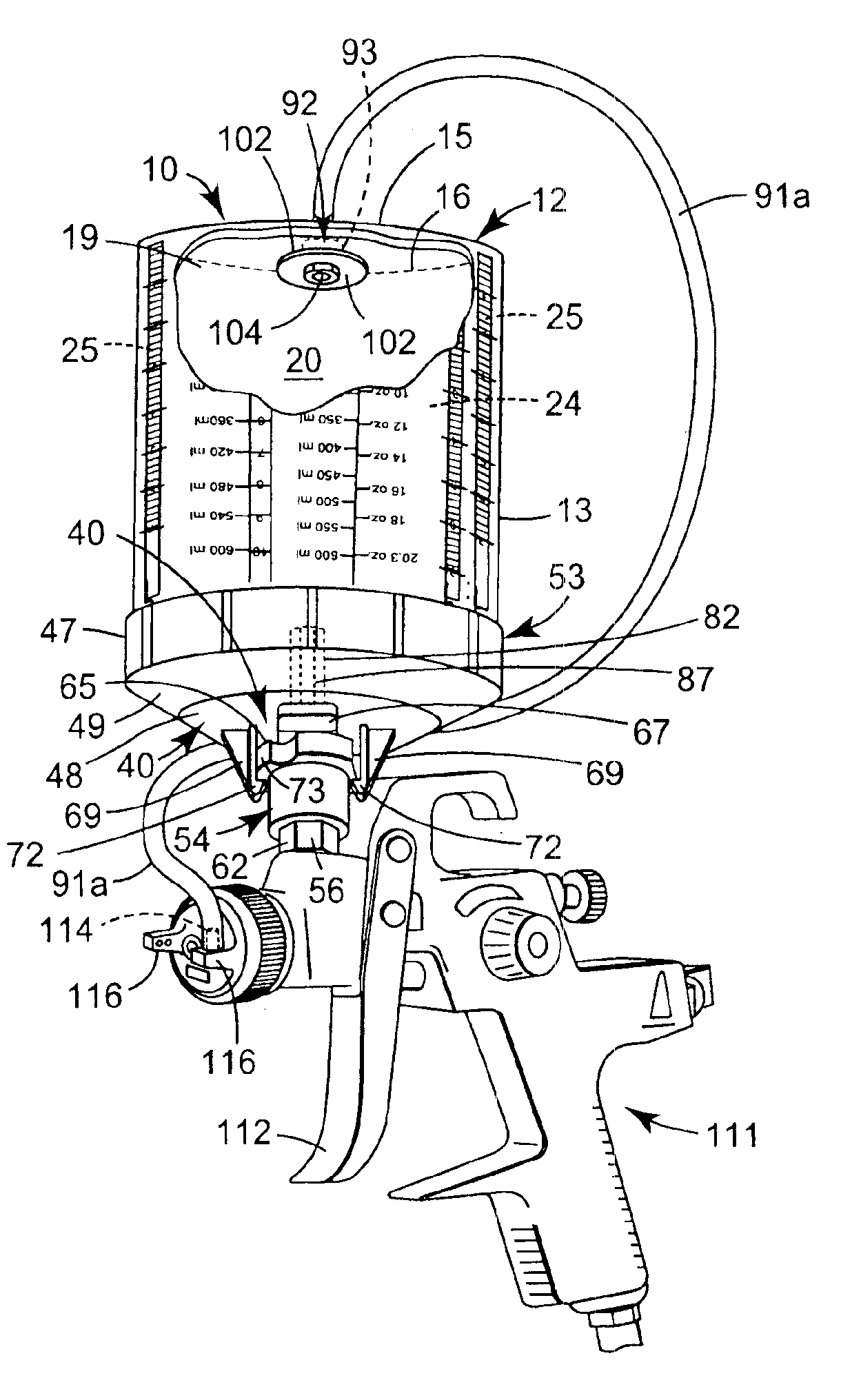
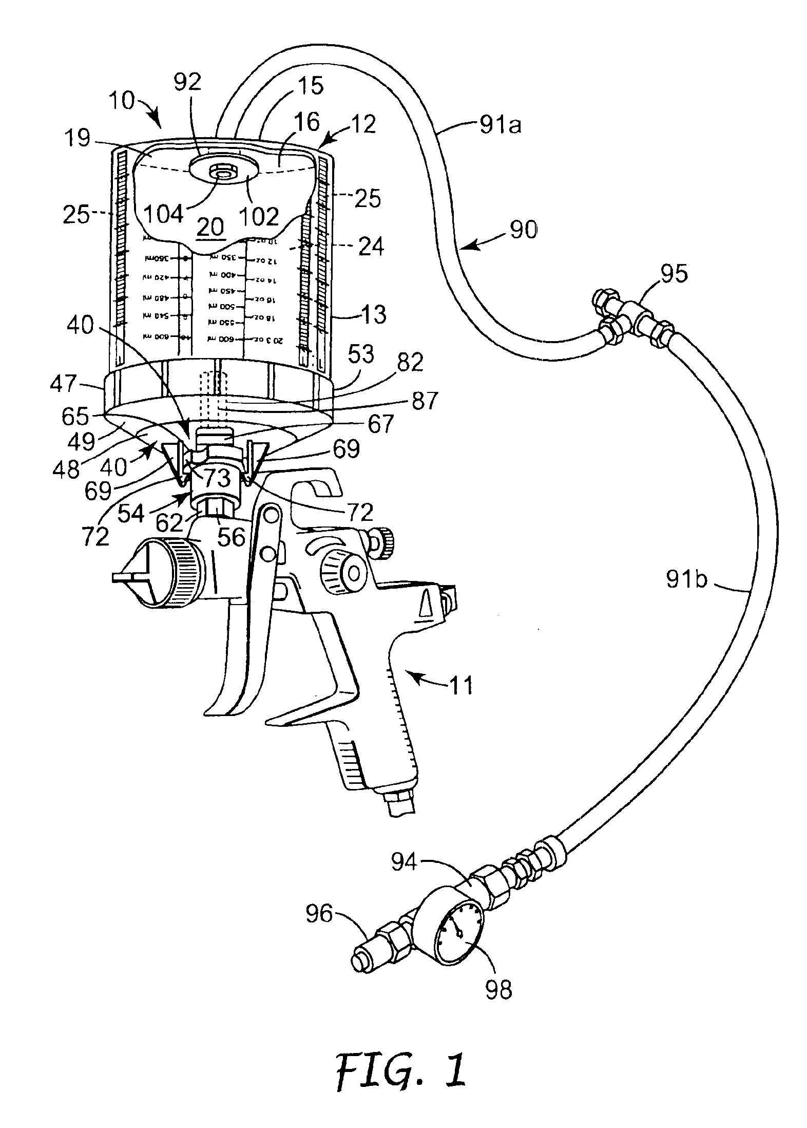
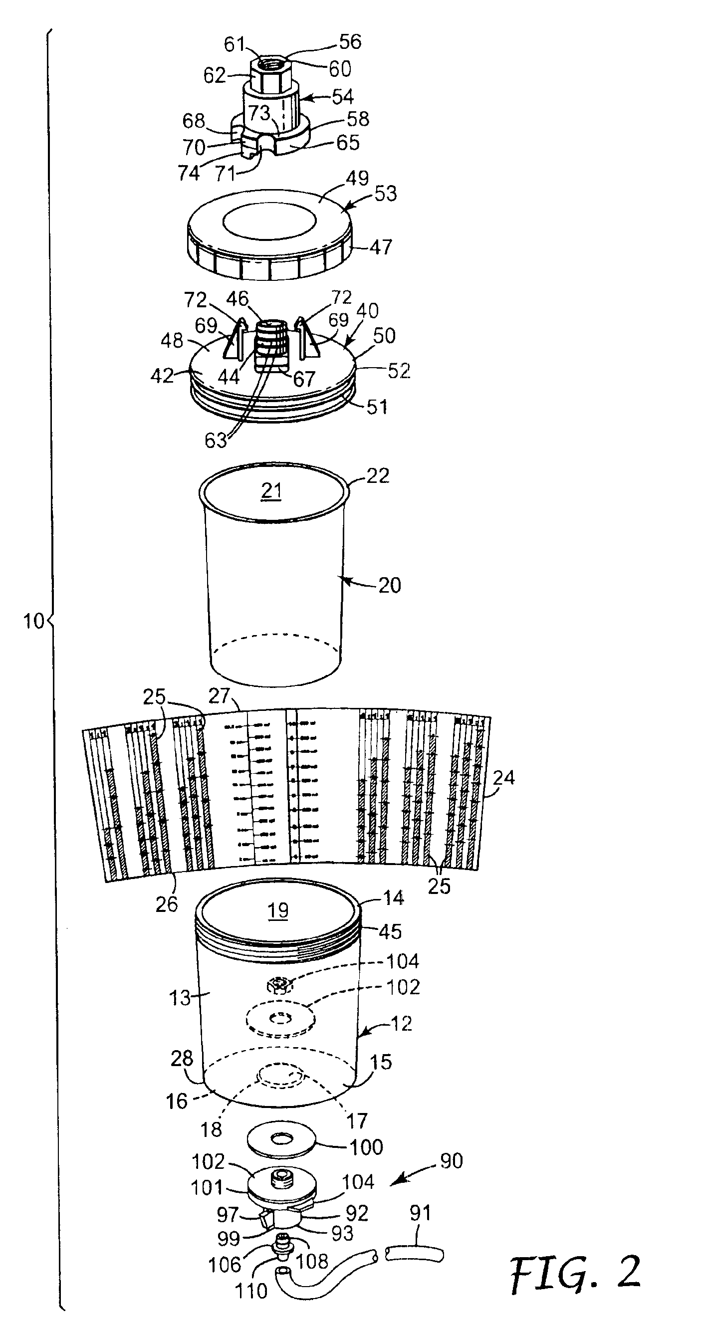
[0017]Referring now to FIGS. 1 and 2 of the drawing there is illustrated a liquid supply assembly according to the present invention generally designated by the reference numeral 10. As is illustrated in FIG. 1, that liquid supply assembly 10 can be used to supply liquid to be sprayed to a conventional gravity fed liquid spraying device or spray gun 11 such as the spray gun 11 illustrated that is commercially designated a “SATA” (t.m.) NR-95″ spray gun and is commercially available from Sata, Farbspritzechnik GmbH & Co., Kornwestheim, Germany).

[0018]The liquid supply assembly 10 includes a container 12 of stiff visually transparent polymeric material (e.g., injection molded of clarified polypropylene to have about 0.047 inch or 1.2 mm thick walls). The container 12 comprises a generally cylindrical side wall 13 having top and bottom ends 14 and 15, and a bottom wall 16 extending across the bottom end 15 of the side wall 13. The bottom wall 16 has a central circular through opening 1...


PUM


Abstract

An assembly for feeding liquid to the inlet port of a liquid spraying device or spray gun. The assembly includes a stiff container that defines an opening into a cavity in the container, and a flexible liner positioned within the cavity in the container has an outer surface generally corresponding in shape to the inner surface of the container, an inner surface defining a cavity in the liner, and an annular lip along the top end of the side wall defining an opening into the cavity in the liner. An included adapter assembly has a central portion with a through opening that is adapted to engage the inlet port of a liquid spraying device, a transverse portion including a peripheral part adapted for engagement within the flexible liner adjacent said top end of the container, and means for sealing the flexible liner around the peripheral part of the adapter assembly. An air supply assembly connected to the container supplies air at a relatively low pressure (e.g., in the range of about 0.5 to 8 pounds per square inch or 3.5 to 55 kilopascals) between the outer surface of the flexible liner and the inner surface of the container which improves the flow of liquids through the liquid spraying device or spray gun to which the assembly is attached, and allows that spraying device or spray gun to be used in any orientation.

Description

FIELD OF THE INVENTION[0001]The present invention relates to the liquid supply assemblies that supply liquids to be sprayed (e.g., paint) to liquid spraying devices such as spray guns, and in one aspect, to such liquid supply assemblies in which the liquids are supplied to the liquid spraying devices or spray guns from within collapsible liners.BACKGROUND OF THE INVENTION[0002]Various gravity feed liquid supply assemblies have been used for supplying liquids to be sprayed to liquid (e.g., paint) spraying devices such as spray guns, including the liquid supply assembly including a collapsible liner that is described in International Publication Number WO 98 / 32539 (Joseph) of Jul. 30, 1998, the content whereof is incorporated herein by reference. That liquid supply assembly described in WO 98 / 32539 includes a container of stiff polymeric material comprising a generally cylindrical side wall and a bottom wall at a bottom end of the side wall with an opposite top end of the side wall de...

Claims


Application Information

Patent Timeline
IPC IPC(8): B05B7/24
CPCB05B7/241B05B7/2467B05B7/2478B05B7/2481
Inventor JOSEPH, STEPHEN C. P.BROTHERTON, GARYROTHRUM, ROBERT J.
Owner 3M INNOVATIVE PROPERTIES CO
Learn More