Sway brace fitting

a technology of sway braces and fittings, which is applied in the direction of couplings, curtain suspension devices, manufacturing tools, etc., can solve the problems of limiting the use of fittings, reducing the cost of sway braces, and restricting the load-carrying capacity of fittings, so as to facilitate the attachment of fittings

Inactive Publication Date: 2005-10-11
TOLCO
View PDF48 Cites 19 Cited by
  • Summary
  • Abstract
  • Description
  • Claims
  • Application Information

AI Technical Summary

Benefits of technology

[0011]A sway brace fitting constructed in accordance with the present invention overcomes the afore-noted disadvantages by incorporating a pair of spaced jaws which can accommodate a variety of braces, along with a set screw, preferably having a cone point and preferably being angled, for securely and deformingly engaging the brace wall. Additionally, a yoke is incorporated with the sway brace fitting which facilitates attachment of the fitting to the desired surface.
[0012]The sway brace fitting is part of a bracing system used to prevent swaying of pipes and other loads suspended below ceilings and beams. The fitting firmly grips one end of the brace while the other end of the brace is connected to the load. The yoke is used to attach the sway brace fitting to the ceiling or beam.
[0015]The set screw preferably engages the collar plate threaded opening such that it is disposed substantially in line with the recess of the center plate and is threadably movable in the opening. The first jaw recess preferably has a sharp corner which engages the deformed material of the brace wall to resist withdrawal of the brace from between the jaws. Preferably, the threaded opening is angled, which in turn angles the set screw when it is engaged in the threaded opening. The angle orientation is such that when a tensile load is applied to the brace, the set screw is forced more tightly into the brace wall. Additionally, the center plate preferably has an edge positioned closely adjacent to the set screw which prevents movement of the set screw when a compressive load is applied to the brace. Moreover, the center plate support resists bending of the collar plate second jaw and advantageously orients a substantial portion of the applied load parallel to the plane of the center plate. Preferably, the set screw has a cone point for firmly lodging in to the wall of the brace, thereby securely clamping the brace against the center plate first jaw.
[0017]A second strip of metal is stamped into a clamp center plate. The stamping includes punching a hole at one end of the center plate while the other end is formed into a jaw which has a slot adjacent to it. The closed end of the collar plate slot is inserted into the slot in the center plate so that the hole in the center plate is aligned with the U-shaped ends of the legs of the collar plate and the closed end of the slot in the collar plate fits within the slot formed in the center plate. A set screw is then threaded into the threaded opening of the collar plate, and a connector pin may optionally be inserted into the hole of the center plate, to form a sway brace fitting including the center plate, the collar plate and the set screw. This preferred method for manufacturing the fitting is especially suited for automated assembly lines, wherein the simplicity and speed of the manufacturing process produces a desirably inexpensive end-product.
[0019]In accordance with another embodiment, a sway brace fitting is provided. The sway brace fitting generally comprises a clamp with a body portion, a lower jaw and a screw. The lower jaw is on the body portion of the clamp. The lower jaw has an inner surface with a length. The screw has a threaded portion and is threadably mounted on the clamp. The screw is movable towards the inner surface of the lower jaw to grip a wall of a brace between the lower jaw and the screw. A recess on the inner surface of the lower jaw provides clearance space for deformed material created by the screw engaging the brace. The recess has a length smaller than the length of the inner surface of the lower jaw.
[0025]Those of ordinary skill in the art will readily recognize the versatility of the present invention. The jaws of the sway brace fitting of the present invention are attachable to a variety of braces, for example, bracing pipes, angle irons, channels, plates and the like. Additionally, the fitting described herein can reliably withstand substantial loads, is simply and expeditiously installable, is economical to manufacture and is desirably inexpensive.

Problems solved by technology

Such a design limits the use of the fitting with threaded pipes only and can also restrict its load-carrying capability.
Additionally, the use of a threaded pipe, as compared to using a similar unthreaded pipe, undesirably adds to the cost of the sway brace system.
Disadvantageously, the labor and / or time consumed by such an installation is an undesirable additional expense.
While some of the above-mentioned prior art sway brace fittings may be attachable to braces other than a bracing pipe, such as angle irons or channels, this attachment would generally require the use of an additional structural attachment component, thereby undesirably adding to the complexity and cost of the sway brace system and its installation.

Method used


Image

  • Sway brace fitting
  • Sway brace fitting
  • Sway brace fitting

Examples


Embodiment Construction

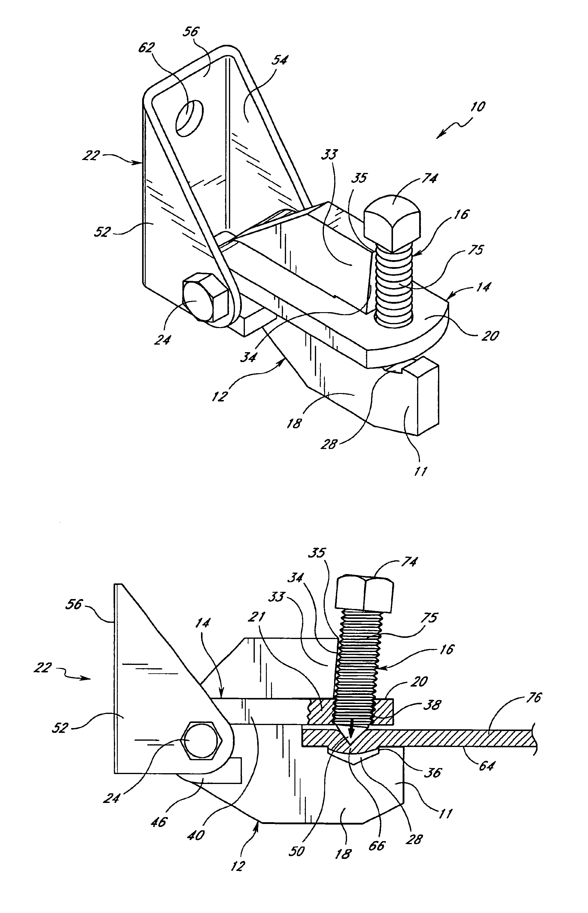
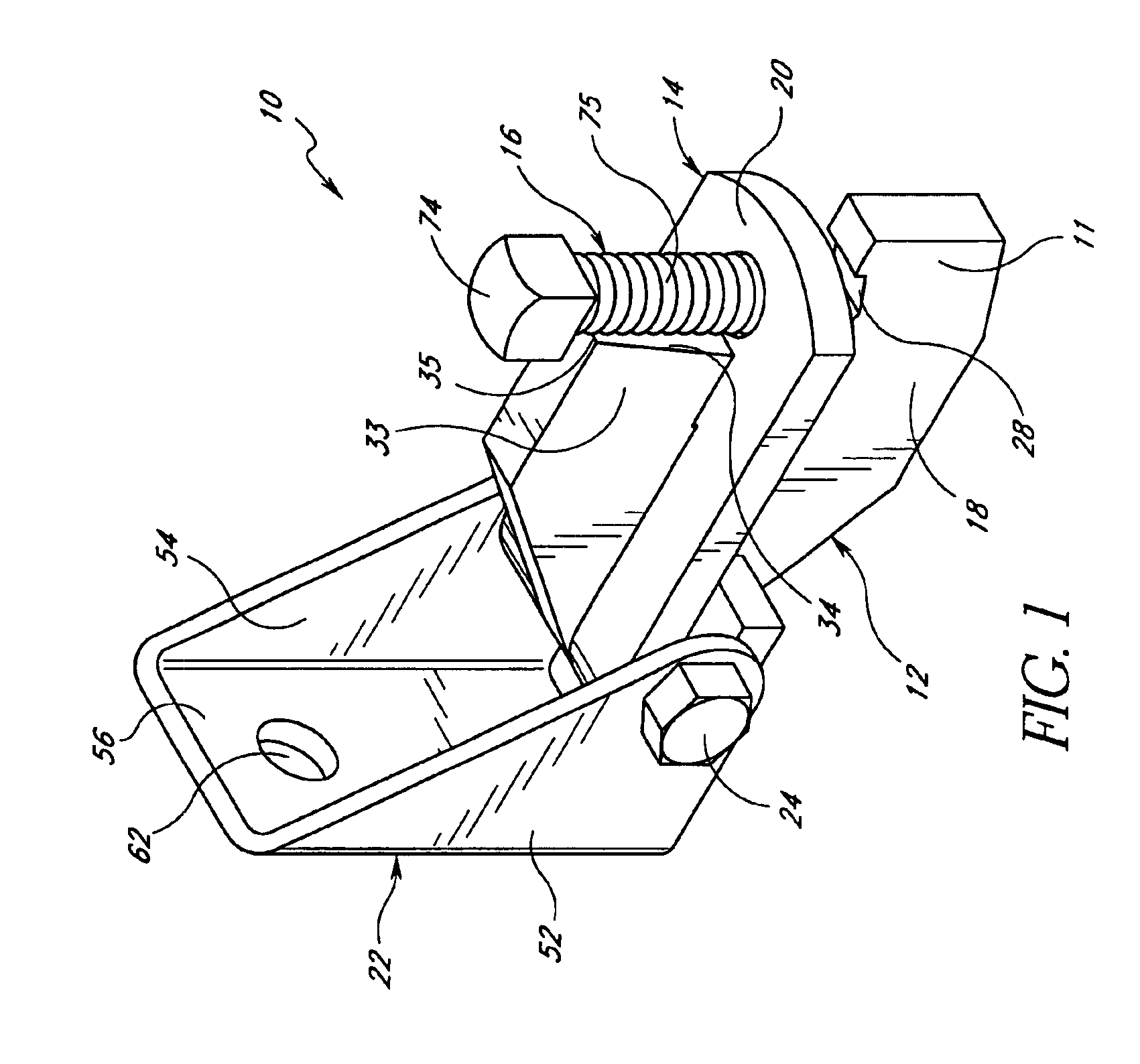
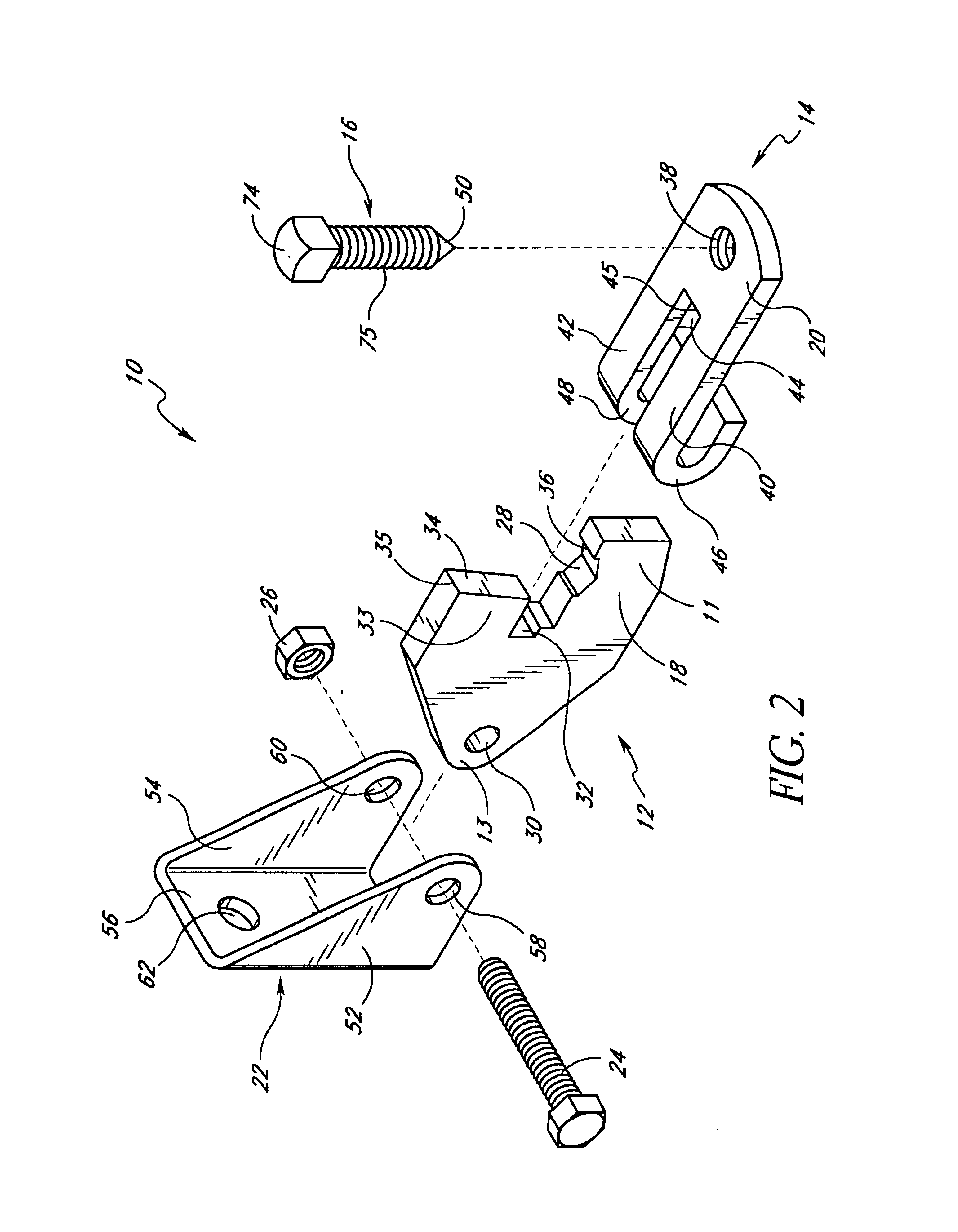
[0035]Referring to the drawings, and particularly to FIGS. 1 to 3, a preferred embodiment of a sway brace fitting 10 constructed and assembled in accordance with the invention comprises a clamp center plate 12, a clamp collar plate 14, a set screw 16, a bolt 24 and a nut 26. The fitting 10 securely and deformingly grips a brace wall 64 of a brace 76. Additionally, a yoke 22 is incorporated with the sway brace fitting 10 of the present invention.

[0036]As schematically illustrated in FIGS. 4A and 4B, the sway brace fitting 10 is part of a bracing system 80 used to prevent swaying of pipes and other loads, for example a pipe 76, suspended from ceilings and beams. The fitting 10 firmly grips one end 82 of the brace 76 while the other end 84 of the brace 76 is connected to the load, for example the pipe 76. The yoke 22 is used to attach the sway brace fitting 10 to the ceiling or beam.

[0037]As best shown in FIGS. 2 and 6, preferably, one end 11 of the clamp center plate 12 includes a fir...


PUM


Abstract

A versatile sway brace fitting, includes a pair of spaced jaws, for firmly and deformingly gripping a brace, and a method for manufacturing the fitting. The fitting can withstand substantial loads and is adaptable to receive a variety of braces such as bracing pipes, angle irons, channels, plates, among others. The fitting includes a set screw, preferably angled, and a sharp-cornered recess which assist in resisting withdrawal of the brace from the jaws. The method of manufacturing is desirably simple and expeditious, thereby ensuring that the fitting is inexpensive.

Description

RELATED APPLICATION[0001]This application is a divisional of U.S. application Ser. No. 09 / 929,602, filed Aug. 14, 2001 now U.S. Pat. No. 6,517,030, which is a continuation of U.S. application Ser. No. 09 / 301,299, filed Apr. 28, 1999, now U.S. Pat. No. 6,273,372, issued Aug. 14, 2001, the entirety of each one which is hereby incorporated by reference herein.BACKGROUND OF THE INVENTION[0002]1. Field of the Invention[0003]The present invention relates to devices for bracing pipes and other loads, suspended below ceilings and beams, against sway and seismic disturbances, and, in particular, to a sway brace fitting for firmly gripping a brace.[0004]2. Background of the Related Art[0005]There is a multitude of products in the market utilized by building and plumbing contractors for bracing and supporting pipes, ducts, sprinkler systems, fans, air-conditioners and other loads from ceilings and beams. These products include clamps, braces, hooks, straps, plates, brackets, among other items....

Claims


Application Information

Patent Timeline
Patent Type & Authority Patents(United States)
IPC IPC(8): F16L3/14
CPCB25B5/006B25B5/101F16L3/015F16L3/133F16L3/24F16L3/127F16B2/065Y10T403/7041Y10T403/7037F16L3/243
Inventor HEATH, RICHARD W.
Owner TOLCO
Why Eureka
Try Eureka