Foil bearing

a technology of oil bearings and bearings, applied in the direction of sliding contact bearings, machines/engines, liquid fuel engines, etc., can solve the problems of difficult to vary the preload and excessive force tending to concentrate on the root, and achieve the effect of avoiding excessive force and stable rotation of the rotating member

Inactive Publication Date: 2005-10-11
HONDA MOTOR CO LTD
View PDF3 Cites 11 Cited by
  • Summary
  • Abstract
  • Description
  • Claims
  • Application Information

AI Technical Summary

Benefits of technology

[0007]In view of such problems of the prior art, a primary object of the present invention is to provide a foil bearing that can allow stiffness or preload of foils against a rotating member, such as a rotor shaft, to be varied in a wide range to ensure stable rotation of the rotating member at both low and high rotation speed regions, while avoiding an excessive force applied on a part of each foil.
[0008]A second object of the present invention is to provide such a foil bearing simple in structure and low at cost.
[0010]Thus, because the abutting member is provided so as to extend from the moveable member toward the circumferentially extending portion of the foil through the through-hole formed in the stationary mount member and the surface of the moveable member contacting the one end of the abutting member is provided with a cam surface, rotation of the moveable member can vary the length of the other end portion of the abutting member projecting out from the surface of the stationary mount member toward the foil. Therefore, by varying the angular position of the moveable member, it is possible to adjust a position at which the abutting member abuts the circumferentially extending portion of the foil when an externally applied force causes the foil to flex outwardly (or away from the rotating member). This has substantially the same effect as varying the stiffness of the foil. In a case where the present invention is applied to a journal bearing and / or thrust bearing of a gas turbine engine, for example, the angular position of the moveable member may be controlled according to the rotational speed of the gas turbine engine so that an appropriate stiffness (or range of movement) is provided to the foil and a preferable bearing property is achieved for a wide range from low to high rotational speed regions. The abutting member limits the flexing movement of the associated foil by abutting the circumferentially extending portion thereof, and thus it is possible to prevent an excessive force from being concentrated on the root portion of the foil.

Problems solved by technology

In such a foil bearing, however, the preload of the foils against the rotor shaft relies upon an elasticity of each foil, and thus it is difficult to vary the preload in a sufficiently large range, and further, an excessive force tends to concentrate on a root portion of each cantilevered foil.

Method used


Image

  • Foil bearing
  • Foil bearing
  • Foil bearing

Examples


Embodiment Construction

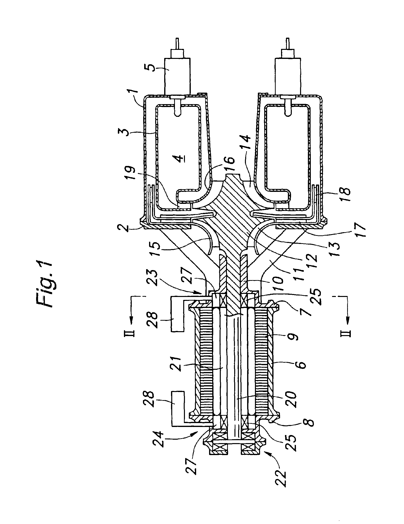
[0031]FIG. 1 is a longitudinal cross sectional view for showing a micro gas turbine generator to which the present invention is applied. The micro gas turbine generator includes a gas turbine engine as a power source and an electric generator driven by the gas turbine engine. The gas turbine engine comprises an annular main housing 1 of which end remote from the generator is closed, an end plate 2 attached to an open end of the main housing 1, a perforated annular inner housing 3 coaxially received inside the main housing 1 to define a combustion chamber 4 therein, and a plurality of fuel injectors 5 each having a nozzle end projecting into the combustion chamber 4.

[0032]The generator comprises a cylindrical main housing 6 and a pair of end plates 7 and 8 attached to either axial end of the main housing 6. The main housing 6 coaxially receives a stator coil 9 therein. The end plate 7 facing the gas turbine engine is provided with a tubular extension 10 extending centrally from the e...


PUM


Abstract

In a foil bearing (23) having a plurality of foils (26) disposed in a gap between a rotating member (12) and a stationary mount member (25), a moveable member (27) is disposed on a side of the stationary member opposite to the rotating member so as to be rotatable with respect to the stationary mount member, abutting members (30) extend from the moveable member toward the associated foils through respective through-holes formed in the stationary mount member, and a surface of the moveable member with which one end of each abutting member is in contact is provided with a cam surface. In such a structure, by rotating the moveable member and thus changing the length of the abutting members projecting out from the surface of the stationary mount member, it is possible to vary the range of movement of the foils and practically vary the stiffness of the same.

Description

TECHNICAL FIELD[0001]The present invention relates to foil bearings. Particularly, the present invention relates to foil bearings suitable for use as a journal bearing or thrust bearing for a rotor shaft of a micro gas turbine generator.BACKGROUND OF THE INVENTION[0002]It has been conventionally known to use a foil bearing as a bearing for a rotor shaft. A foil bearing typically comprises a housing surrounding the rotor shaft and a plurality of foils disposed in a space or gap between the rotor shaft and the housing and arranged in a circumferential direction in such a manner that each of the foils is attached to the housing in a cantilever fashion with its free end being urged toward the rotor shaft. As the rotor shaft rotates, a fluid such as ambient air is drawn in between the rotor shaft and the foils, creating a fluid film between an outer surface of the rotor shaft and the foils to allow the rotor shaft to rotate with low friction. Such a foil bearing that supports a load of t...

Claims


Application Information

Patent Timeline
IPC IPC(8): F16C17/00F16C17/12F02C7/06F01D25/16F04D29/056F16C27/02
CPCF16C17/024F16C17/042F16C43/02F16C25/02F16C2360/23
Inventor MATSUNAGA, MINORU
Owner HONDA MOTOR CO LTD
Why Eureka
Try Eureka