Ion beam utilization during scanned ion implantation

a technology of ion beam and ion implantation, which is applied in the direction of irradiation devices, electric discharge tubes, electrical equipment, etc., can solve the problems of reducing throughput, wasting resources, and reducing the size of the ion implanter, so as to reduce the risk of overshoot, improve throughput or yield, and save resources

Active Publication Date: 2005-10-11
AXCELIS TECHNOLOGIES
View PDF6 Cites 32 Cited by
  • Summary
  • Abstract
  • Description
  • Claims
  • Application Information

AI Technical Summary

Benefits of technology

[0005]The present invention is directed to a serial implantation process for implanting ions into a workpiece in a manner that conserves resources and improves throughput or yield. The workpiece is moved back and forth through a substantially fixed ion beam in a controlled manner to mitigate “overshoot”. More particularly, the workpiece is oscillated along a fast scan path while being moved along a substantially perpendicular slow scan path. A scan pattern generated by the selective movement of the workpiece approximates the shape of the workpiece such that the entire workpiece is implanted with ions. In this manner, overshoot is

Problems solved by technology

Processing batches of substrates in such a manner, however, generally makes the ion

Method used


Image

  • Ion beam utilization during scanned ion implantation
  • Ion beam utilization during scanned ion implantation
  • Ion beam utilization during scanned ion implantation

Examples


Embodiment Construction

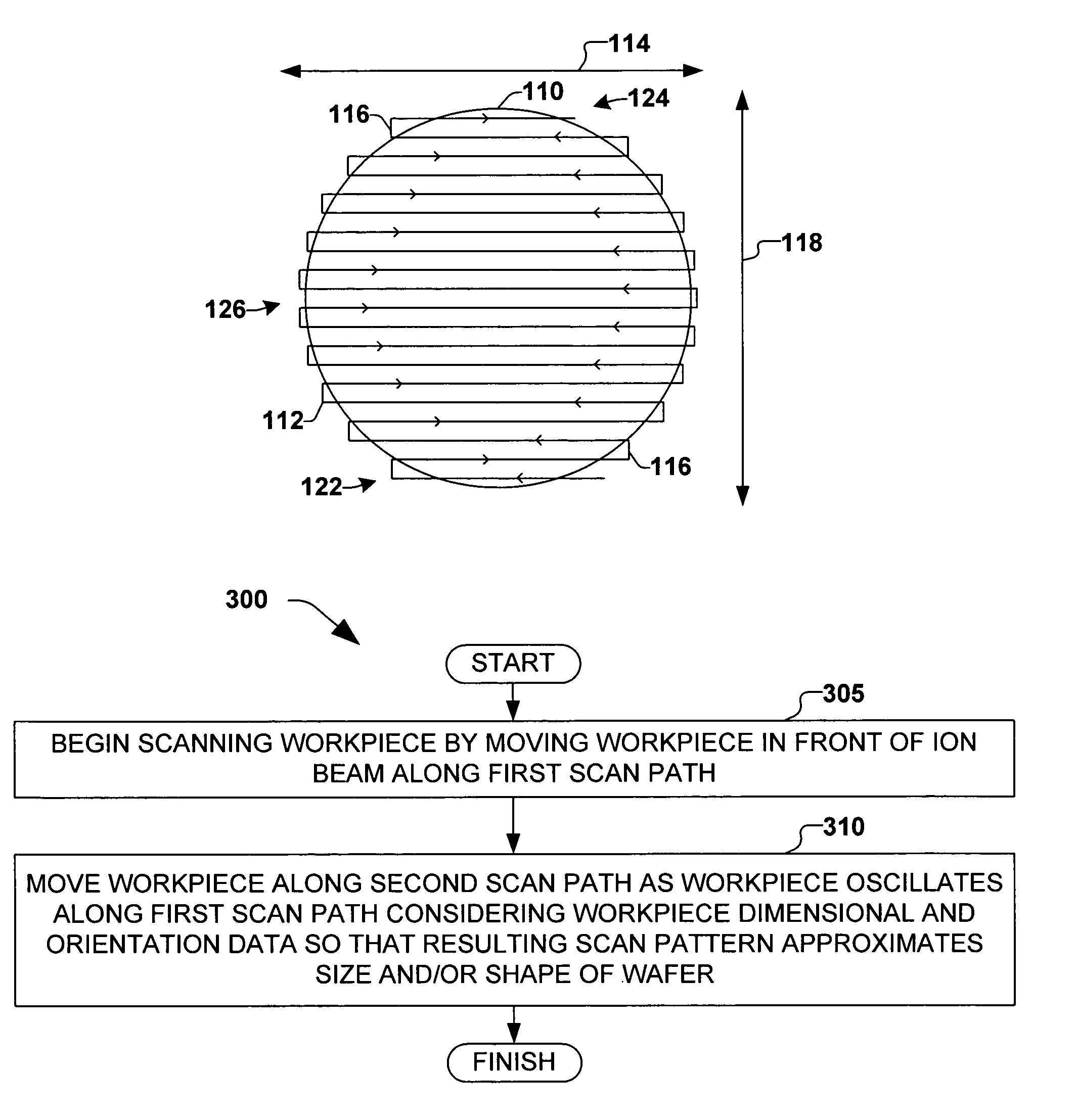
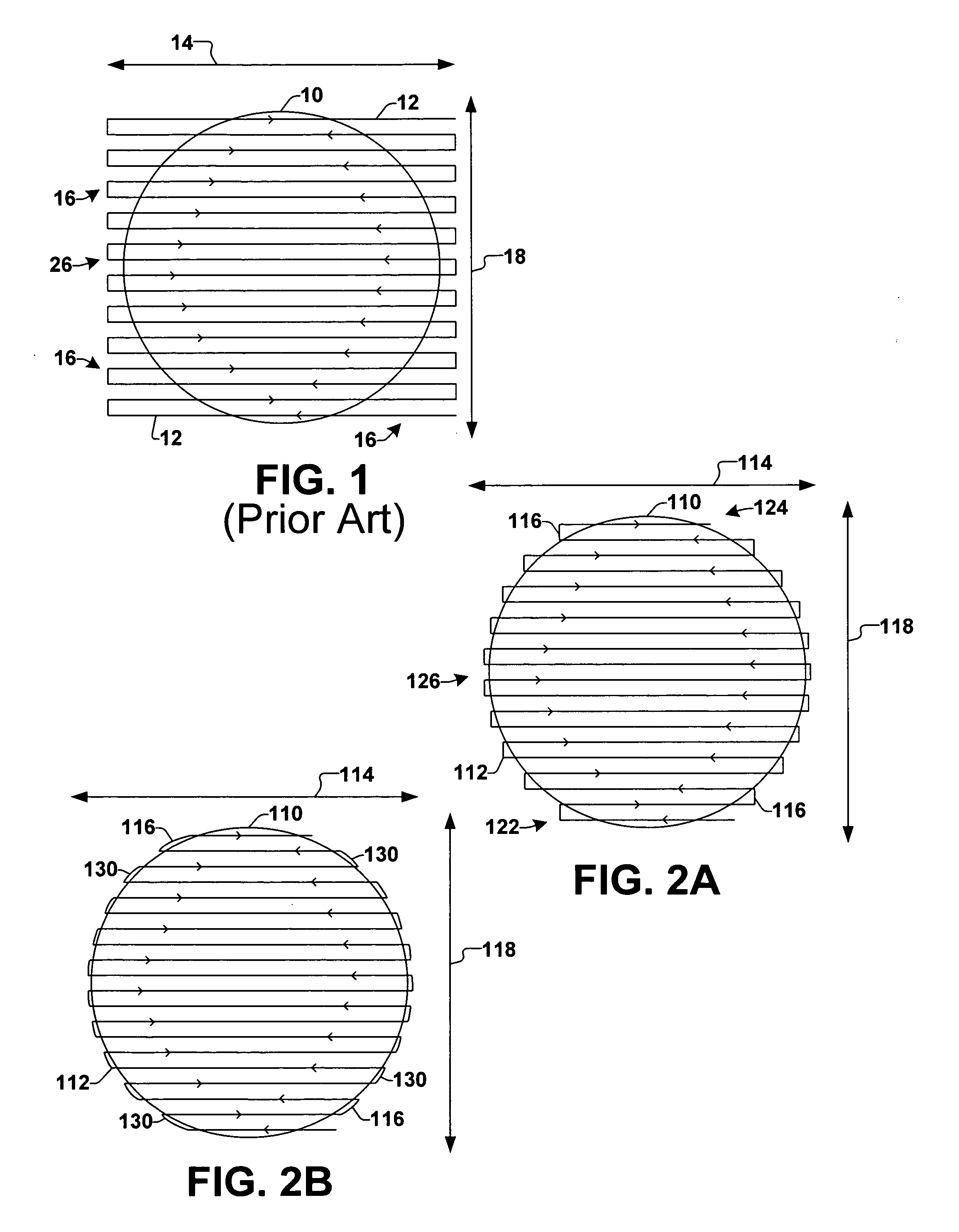
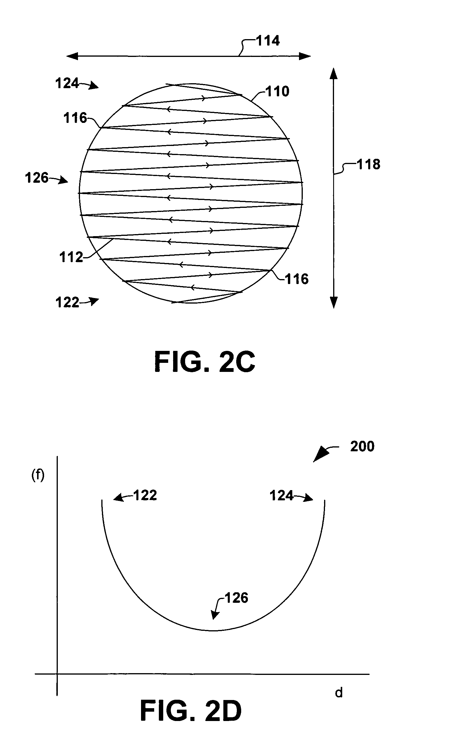
[0020]The present invention is directed towards moving a workpiece or substrate relative to a substantially fixed ion beam so that a scan pattern produced thereby resembles the shape of the workpiece. One or more aspects of the present invention will now be described with reference to drawing figures, wherein like reference numerals are used to refer to like elements throughout. It should be understood that the drawing figures and following descriptions are merely illustrative and that they should not be taken in a limiting sense. In the following description, for purposes of explanation, numerous specific details are set forth in order to provide a thorough understanding of the present invention. It will be evident to one skilled in the art, however, that the present invention may be practiced without these specific details. Thus, it will be appreciated that variations of the illustrated systems and methods apart from those illustrated and described herein may exist and that such v...


PUM


Abstract

The present invention is directed to implanting ions in a workpiece in a serial implantation process in a manner that produces a scan pattern that resembles the size, shape and/or other dimensional aspects of the workpiece. This improves efficiency and yield as an ion beam that the workpiece is oscillated through does not significantly “overshoot” the workpiece. The scan pattern may be slightly larger than the workpiece, however, so that inertial effects associated with changes in direction, velocity and/or acceleration of the workpiece as the workpiece reverses direction in oscillating back and forth are accounted for within a small amount of “overshoot”. This facilitates moving the workpiece through the ion beam at a relatively constant velocity which in turn facilitates substantially more uniform ion implantation.

Description

FIELD OF THE INVENTION[0001]The present invention relates generally to semiconductor processing systems, and more particularly to controlling motion of a substrate relative to an ion beam during ion implantation.BACKGROUND OF THE INVENTION[0002]In the semiconductor industry, various manufacturing processes are typically carried out on a substrate (e.g., a semiconductor workpiece) in order to achieve various results on the substrate. Processes such as ion implantation, for example, can be performed in order to obtain a particular characteristic on or within the substrate, such as limiting a diffusivity of a dielectric layer on the substrate by implanting a specific type of ion. Conventionally, ion implantation processes are performed in either a batch process, wherein multiple substrates are processed simultaneously, or in a serial process, wherein a single substrate is individually processed. Traditional high-energy or high-current batch ion implanters, for example, are operable to ...

Claims


Application Information

Patent Timeline
IPC IPC(8): H01J37/30H01J37/302H01J37/317
CPCH01J37/302H01J37/3171H01J2237/20228H01J2237/30488H01L21/265
Inventor GRAF, MICHAEL A.RAY, ANDREW M.
Owner AXCELIS TECHNOLOGIES
Why Eureka
Try Eureka