Architecture for a central office using IP technology

a technology of ip technology and central office, applied in the field of telephone network architecture, can solve the problems of inability to adapt to ss7, no longer valid assumptions, and unlikely to change quickly enough to realiz

Inactive Publication Date: 2005-10-11
UTSTARCOM INC
View PDF8 Cites 99 Cited by
  • Summary
  • Abstract
  • Description
  • Claims
  • Application Information

AI Technical Summary

Problems solved by technology

Many telecommunications experts, however, have recognized that these assumptions are no longer valid, and have set forth the following new set of assumptions for the communication infrastructure: (1) bandwidth is plentiful and cheap; (2) computation is plentiful and cheap; and (3) terminal devices are “intelligent,” yet capable of providing the necessary security

Method used


Image

  • Architecture for a central office using IP technology
  • Architecture for a central office using IP technology
  • Architecture for a central office using IP technology

Examples


Embodiment Construction

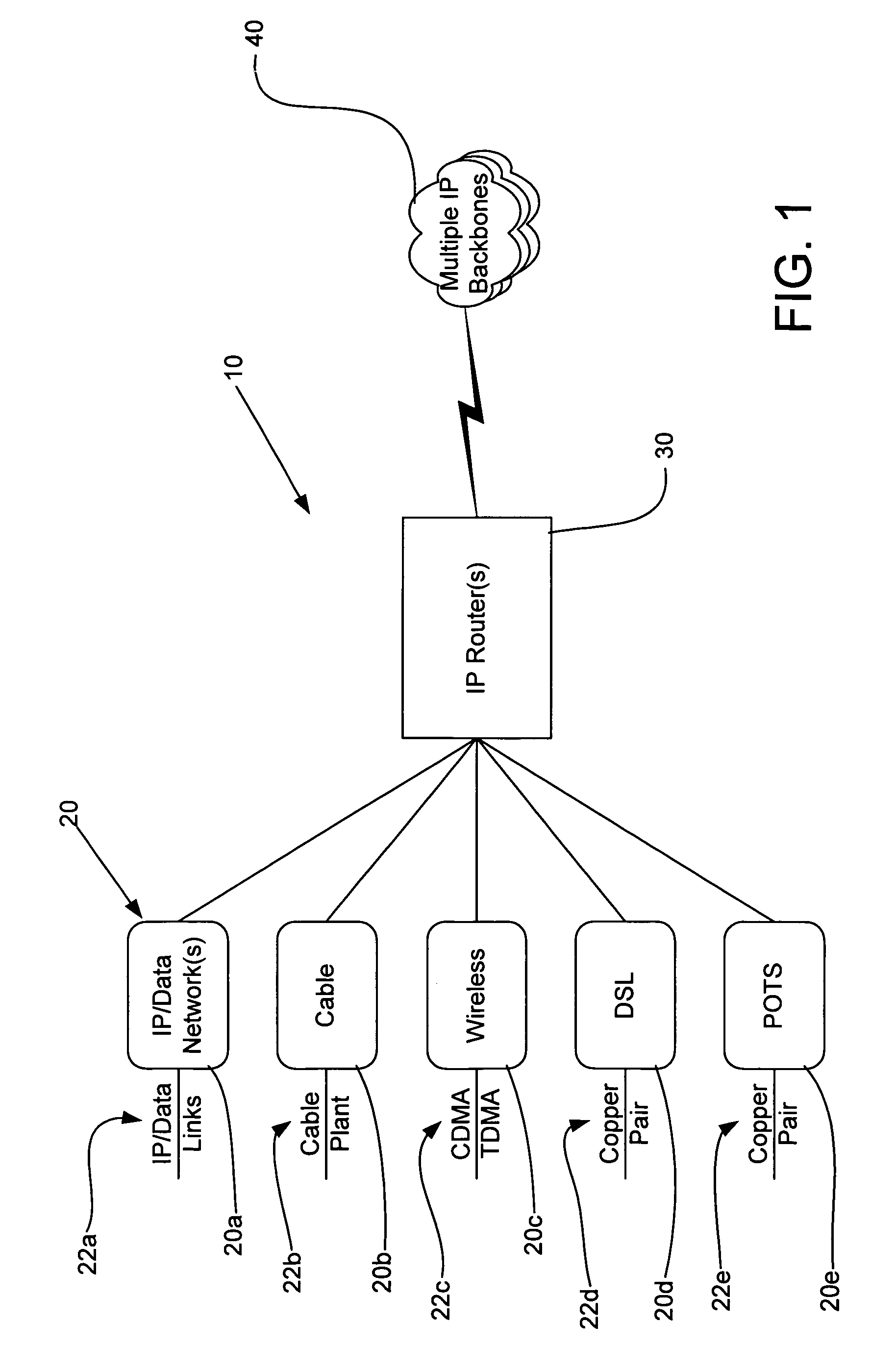
[0020]FIG. 1 is a block diagram illustrating a general architecture for an IPCO 10 of the present invention. This IPCO 10 provides the core for the architectures of the IPCOs shown in FIGS. 2 and 4, and described in detail below. As shown in FIG. 1, the IPCO 10 comprises a plurality of physical media 20 that includes media for one or more IP / data networks 20a, such as IP / data links 22a, media for cable 20b, such as cable plant 22b, media for wireless telephony 20c, such as transmission technology 22c like Code Division Multiple Access (“CDMA”) or Time Division Multiple Access (“TDMA”), media for DSL 20d, such as copper wire pairs 22d, and media for POTS 20e, such as copper wire pairs 22e. The physical media 20 is connected, either directly or indirectly through one or more devices, to one or more IP routers 30, which route packets from / to the physical media 20 to / from one or more IP backbones 40. The IP backbones 40 may include a number of different networks, such as an IP data netw...


PUM


Abstract

A telephony system and method having a switch for analog voice and data signals that is connected to a first network, and a router for routing Internet Protocol packets that is connected to a second network using Internet Protocol addressing. The telephony system and method also includes a telephony gateway that is connected to both the switch and the router for converting analog voice signals into Internet Protocol packets and for converting Internet Protocol packets into analog voice signals, the telephony gateway being connected, and a remote access server that is connected to both the switch and the router for converting analog data signals into Internet Protocol packets and for converting Internet Protocol packets into analog data signals. The switch may have a switch matrix capable of being connected to the Public Switched Telephone Network, a line rack with a plurality of line cards connected to the switch matrix, and a trunk rack with a plurality of trunk cards connected to the switch matrix. The switch matrix may also be connected to the telephony gateway and the remote access server.

Description

FIELD OF INVENTION[0001]This invention relates to architectures for telephone networks. More specifically, it relates to an architecture for a central office (“CO”) using Internet Protocol (“IP”) technology.BACKGROUND OF THE INVENTION[0002]The telephone CO is a primary component of the communication infrastructure. It is the interconnection point for dedicated access lines and shared network resources (i.e., to and from local residences and businesses) with long distance phone carriers and data network providers. A typical CO will serve between 10,000 and 50,000 customers in the local area immediately surrounding the CO. In large metropolitan areas, the customer base may be as large as 100,000 and, in a few instances, upwards of 200,000 subscribers. Each CO is usually owned and operated by an Incumbent Local Exchange Carrier (“ILEC”), but a Competitive Local Exchange Carrier (“CLEC”), such as an Inter-exchange Carrier (“IXC”), may have access to and be responsible for a significant ...

Claims


Application Information

Patent Timeline
IPC IPC(8): H04L12/66H04L12/56
CPCH04L12/56
Inventor SCHUSTER, GUIDO M.SIDHU, IKHLAQ S.MAHLER, JERRY J.GRABELSKY, DAVIDGRABIEC, JACEK A.KOSTAS, THOMAS J.BORELLA, MICHAEL S.
Owner UTSTARCOM INC
Why Eureka
Try Eureka