Frame joiner press system

a press system and frame technology, applied in the field of vnail joiners, can solve the problems of time-consuming, difficult operation, and inability to accurately position the v-nail within the frame joint,

Inactive Publication Date: 2005-10-18
LOGAN CURT
View PDF25 Cites 56 Cited by
  • Summary
  • Abstract
  • Description
  • Claims
  • Application Information

AI Technical Summary

Benefits of technology

[0012]In view of the foregoing disadvantages inherent in the known types of picture frame tools now present in the prior art, the present invention provides a new frame joiner press system construction wherein the same can be utilized for efficiently driving a V-nail into two adjacent members of a picture frame.
[0018]A second object is to provide a frame joiner press system for efficiently driving a V-nail into two adjacent members of a picture frame.
[0020]An additional object is to provide a frame joiner press system that is efficient and reduces the amount of time required to manufacture a picture frame.
[0021]A further object is to provide a frame joiner press system that accurately inserts V-nails into a picture frame joint.
[0026]A further object is to provide a frame joiner press system that accurately presses the V-nails into the frame joint.

Problems solved by technology

The main problem with conventional V-nail joiners is that they are difficult to operate and time consuming.
A further problem with conventional V-nail joiners is that they can only insert a single V-nail into a frame joint.
Another problem with conventional V-nail joiners is that sometimes they do not accurately position the V-nails within the frame joint.
While these devices may be suitable for the particular purpose to which they address, they are not as suitable for efficiently driving a V-nail into two adjacent members of a picture frame.
Conventional V-nail joiners are difficult to operate, time consuming and are inefficient.

Method used


Image

  • Frame joiner press system
  • Frame joiner press system
  • Frame joiner press system

Examples


Embodiment Construction

A. Overview

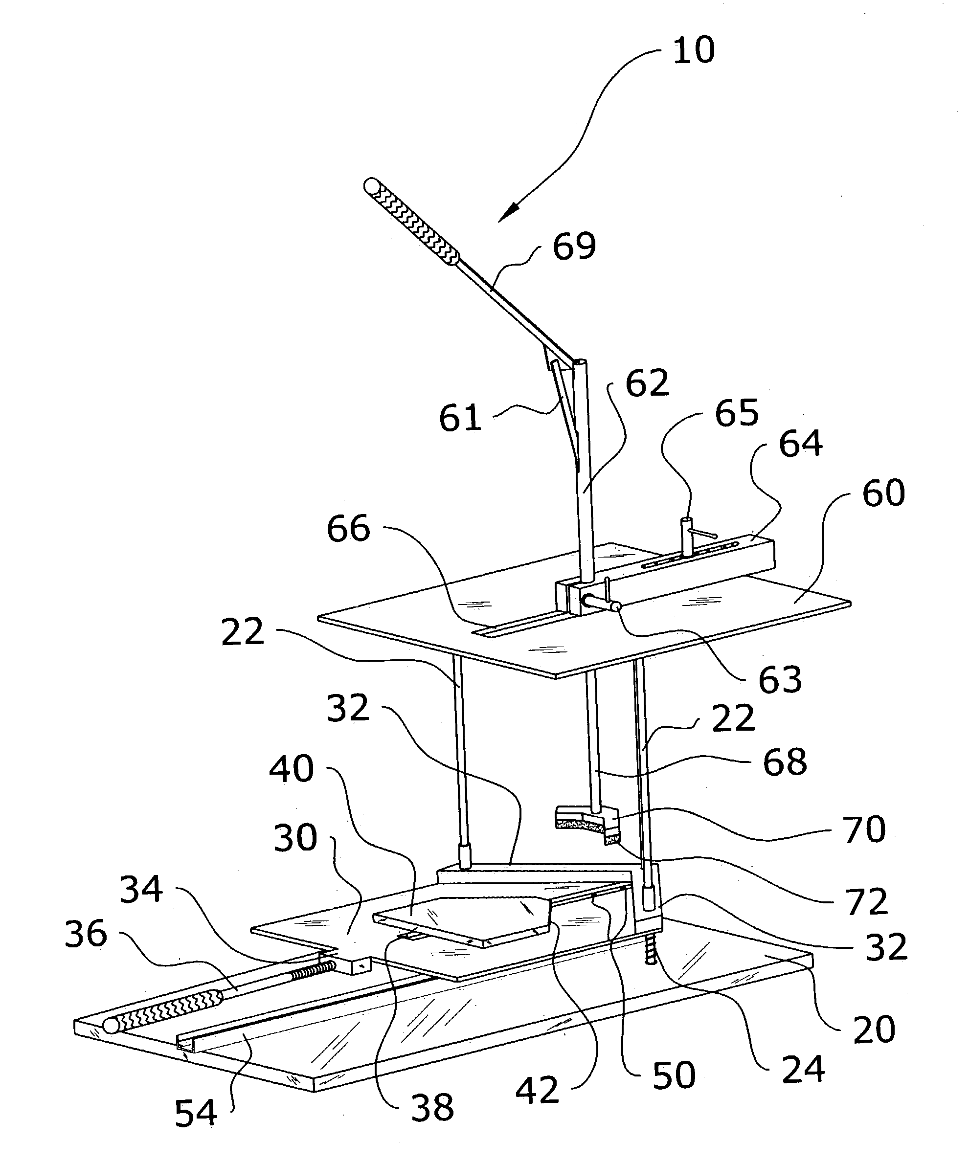
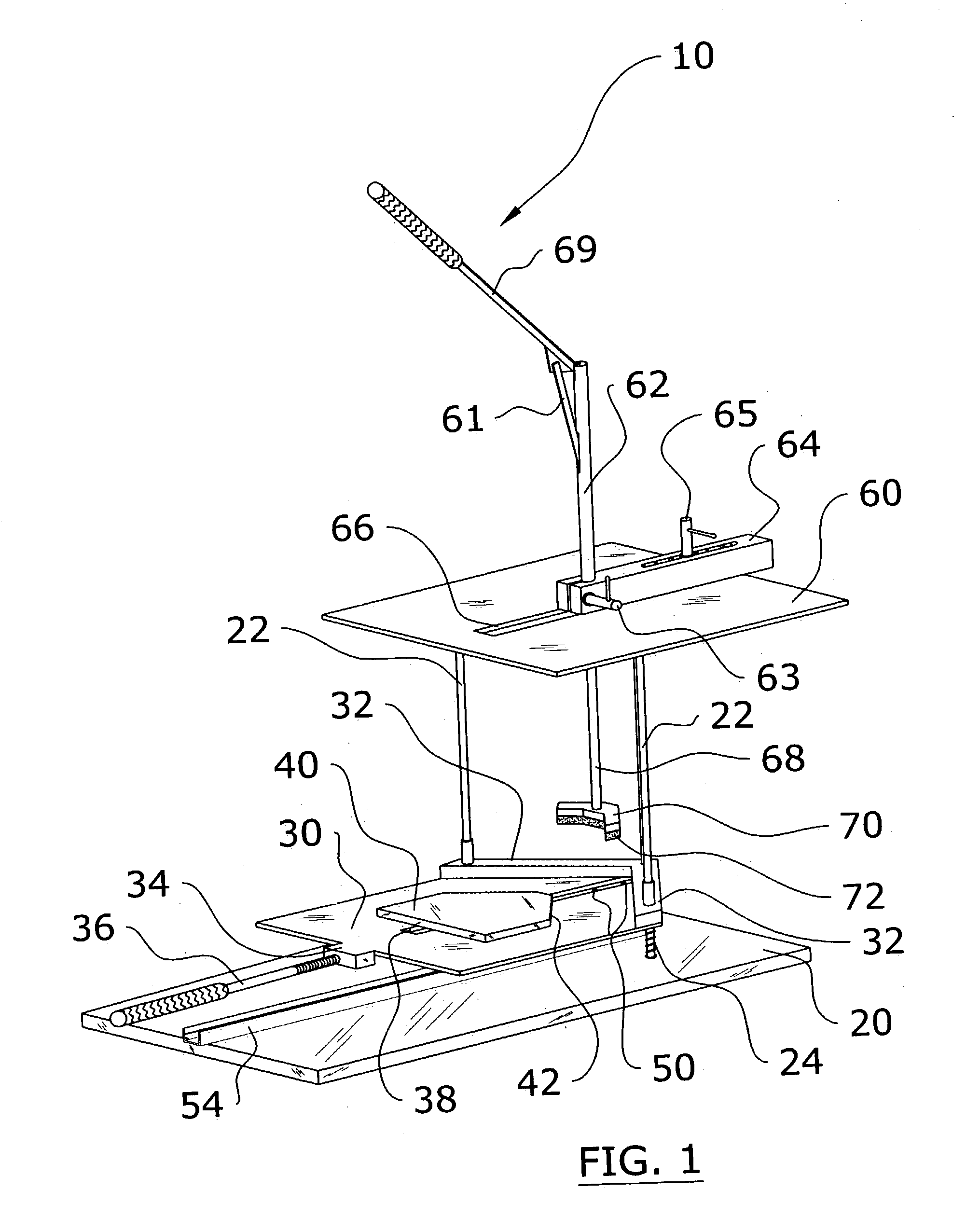
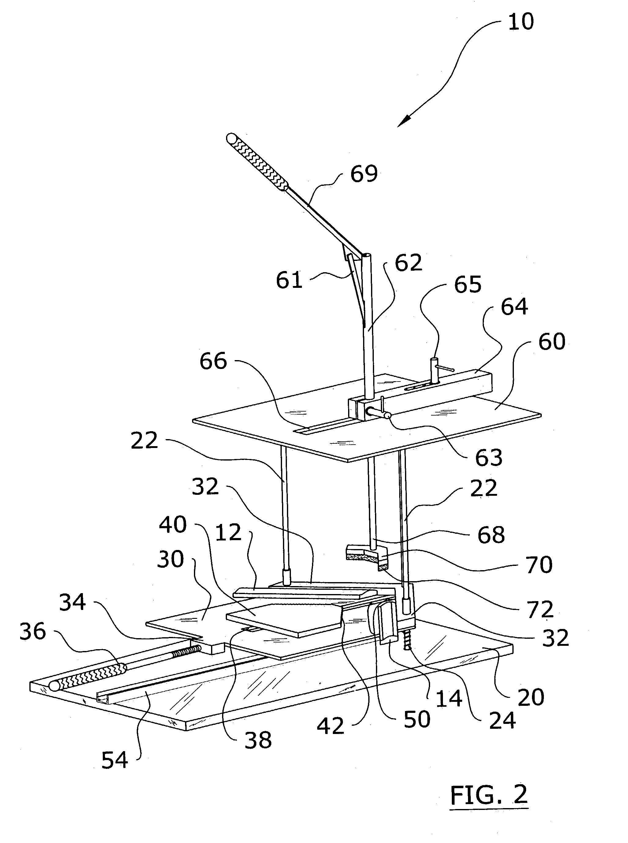
[0044]Turning now descriptively to the drawings, in which similar reference characters denote similar elements throughout the several views, FIGS. 1 through 9 illustrate a frame joiner press system 10, which comprises a base 20, a plurality of support shafts 22 extending upwardly from the base 20, a support platform 30 slidably positioned upon the support shafts 22, a plurality of retaining pins 50 movably positioned within a support housing 52 attached to the base 20, and a leverage structure for applying a downward force upon a pair of frame members. The retaining pins 50 receive one or more V-nails 16 and are springably positioned within the support housing 52. When the frame members are pressed upon the V-nails 16, the retaining pins 50 are depressed into the support housing 52.

B. Base

[0045]FIGS. 1 through 6 of the drawings illustrate the base 20. The base 20 is preferably a flat and broad structure as shown in the figures. However, the base 20 may have various other ...


PUM

PropertyMeasurementUnit
angleaaaaaaaaaa
forceaaaaaaaaaa
resilientaaaaaaaaaa

Abstract

A frame joiner press system for efficiently driving a V-nail into two adjacent members of a picture frame. The frame joiner press system includes a base, a plurality of support shafts extending upwardly from the base, a support platform slidably positioned upon the support shafts, a plurality of retaining pins movably positioned within a support housing attached to the base, and a leverage structure for applying a downward force upon a pair of frame members. The retaining pins receive one or more V-nails and are springably positioned within the support housing. When the frame members are pressed upon the V-nails, the retaining pins are depressed into the support housing.

Description

CROSS REFERENCE TO RELATED APPLICATIONS[0001]Not applicable to this application.STATEMENT REGARDING FEDERALLY SPONSORED RESEARCH OR DEVELOPMENT[0002]Not applicable to this application.BACKGROUND OF THE INVENTION[0003]1. Field of the Invention[0004]The present invention relates generally to V-nail joiners and more specifically it relates to a frame joiner press system for efficiently driving a V-nail into two adjacent members of a picture frame.[0005]2. Description of the Related Art[0006]V-nail joiners for creating picture frames have been in use for years. There are two main types of V-nail joiners: hand-tools and manual presses. Hand-tool joiners are basically comprised of a punch-like structure that receives a single V-nail to be inserted into the two frame members at the joint. The head of the hand-tool typically has a magnet for magnetically retaining the V-nail within the head prior to insertion of the V-nail into the wood frame. The user must either manually press the V-nail ...

Claims


Application Information

Patent Timeline
Patent Type & Authority Patents(United States)
IPC IPC(8): A47G1/06A47G1/10B27F7/00B27F7/02
CPCA47G1/105B27F7/025Y10T29/49902Y10T29/53Y10T29/53978Y10T29/49833Y10T29/53961Y10T29/49899
Inventor LOGAN, CURT
Owner LOGAN CURT
Why Eureka
Try Eureka