Automotive ignition system with sparkless thermal overload protection

a technology of thermal overload protection and ignition system, which is applied in the direction of heat measurement, electrical control, instruments, etc., can solve the problems of difficult to predict an absolute time, spark may occur, and the effect of shutting down techniques generating spark events at the spark plug

Active Publication Date: 2005-10-18
DELPHI TECH IP LTD
View PDF19 Cites 15 Cited by
  • Summary
  • Abstract
  • Description
  • Claims
  • Application Information

AI Technical Summary

Problems solved by technology

Further, current thermal shutdown techniques generate a spark event at the spark plug, following the thermal shutdown, unless an external capacitor is utilized for control purposes.
This is undesirable as a mistimed spark can cause damage to an engine if the spark leads or lags a desired spark timing point by any appreciable amount.
As such, it is difficult to predict an absolute time, following the start of dwell, that a spark may occur.
It should be appreciated that protection of an ignition system at the cost of engine damage is undesirable.
While accomplishing the task of terminating a dwell event without the production of a spark, such systems incur the cost of an external capacitor, increased packaging space required for the capacitor and related interconnect wiring, as well as additional control die area for the required soft shutdown circuitry.
With these types of assemblies, package size, interconnect reliability and cost may result in significant design constraints.
The additional control die area and expense of external capacitors and the related interconnects required for the existing soft shutdown protection implementations are therefore undesirable.

Method used


Image

  • Automotive ignition system with sparkless thermal overload protection
  • Automotive ignition system with sparkless thermal overload protection
  • Automotive ignition system with sparkless thermal overload protection

Examples


Embodiment Construction

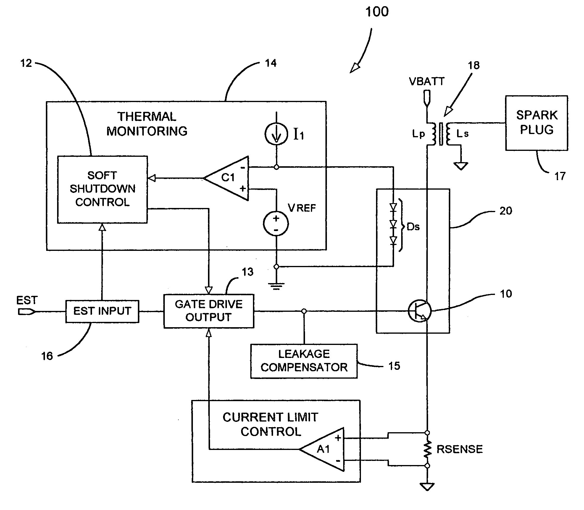
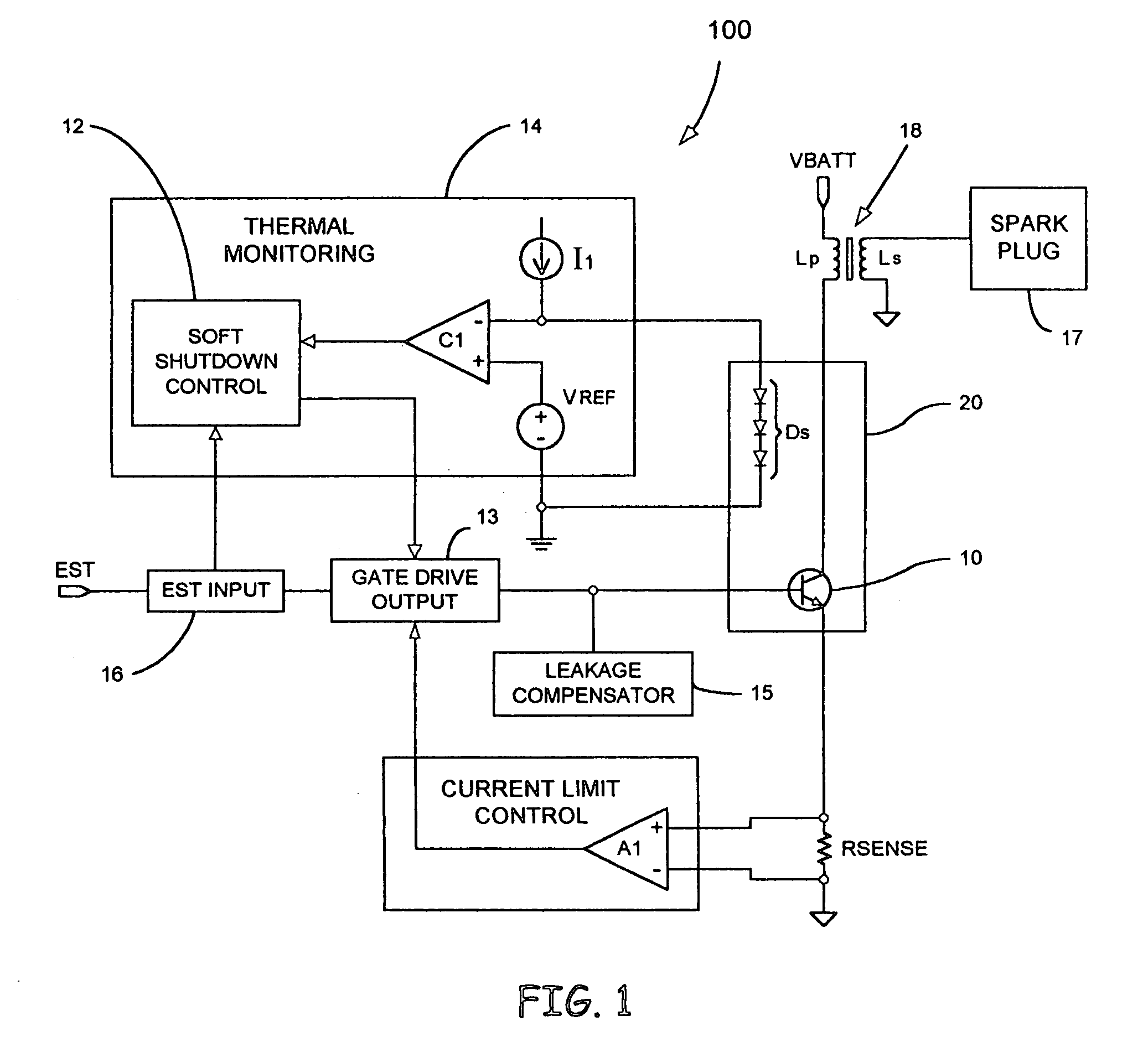
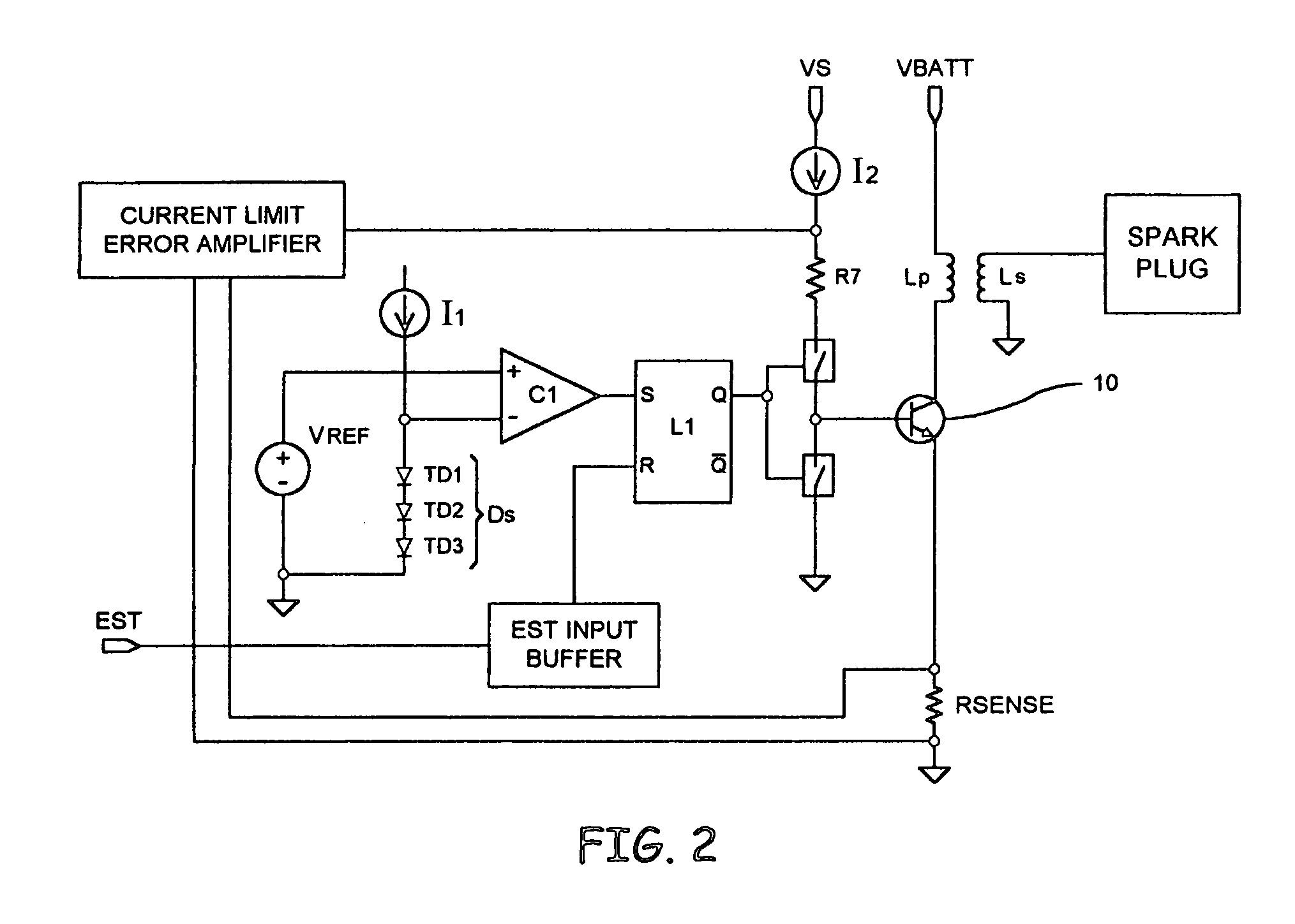
[0013]Various embodiments of the present invention are directed to the detection of a temperature of a switching device, e.g., an insulated gate bipolar transistor (IGBT), in an automotive ignition system and discontinuing a drive signal at a control terminal of the switching device in a controlled fashion, when the temperature of the switching device exceeds a predetermined temperature level, to prevent a spark event. This is accomplished by monitoring the surface temperature of the switching device, via, for example, a plurality of serially connected diodes with known temperature characteristics, integrated within the switching device. These diodes are connected to a control integrated circuit (IC) and are biased by a current generated in the control IC. The control IC monitors a voltage developed across the diode string and if the voltage falls below a predetermined level, indicating a high temperature level, the drive connections to the control terminal of the switching device a...


PUM

PropertyMeasurementUnit
bandgap voltageaaaaaaaaaa
drive currentaaaaaaaaaa
temperatureaaaaaaaaaa

Abstract

An interface for providing thermal overload protection includes a switching device, a temperature indicating device, a drive circuit and a thermal monitoring circuit. The thermal monitoring circuit is coupled across the temperature indicating device and provides a shutdown signal to the drive circuit when the temperature of the switching device is above a predetermined temperature level as indicated by a temperature signal provided by the temperature indicating device. The drive circuit responds to the shutdown signal by removing current sources and current sinks from a control terminal of the switching device at which point leakage currents cause the switching device to reduce a drive current to an inductive load.

Description

TECHNICAL FIELD[0001]The present invention is generally directed to an interface for providing thermal overload protection and, more specifically, to an automotive ignition system with sparkless thermal overload protection.BACKGROUND OF THE INVENTION[0002]Modern automotive ignition systems have provided protection from fault conditions that result in excessively long dwell times by a variety of techniques. For example, some systems have employed time-based protection that terminates a drive signal to an ignition coil current switching device, e.g., an insulated gate bipolar transistor (IGBT), when a predetermined dwell time was exceeded. Other existing systems have employed thermally triggered dwell termination that functions when excessively high temperatures are detected within a switching circuit and / or a control integrated circuit (IC). These methodologies, while generally effective in preventing damage to a control IC and / or a switching circuit, have several drawbacks. For exam...

Claims


Application Information

Patent Timeline
Patent Type & Authority Patents(United States)
IPC IPC(8): F02P3/02F02P3/055G01K7/01
CPCF02P3/055G01K7/01F02D2041/2065F02P3/0453F02P9/002
Inventor KESLER, SCOTT B.FRUTH, JOHN R.
Owner DELPHI TECH IP LTD
Why Eureka
Try Eureka