Molding die and die changing method of the same

a technology of die changing and die, which is applied in the field of molding, can solve the problems of increasing the frequency of replacement, requiring highly frequent replacement of the die, and avoiding shortening the service life of the die, so as to achieve the effect of reducing the time required for die changing

Inactive Publication Date: 2005-10-18
TOYOTA JIDOSHA KK
View PDF11 Cites 23 Cited by
  • Summary
  • Abstract
  • Description
  • Claims
  • Application Information

AI Technical Summary

Benefits of technology

[0020]A molding die and a die changing method of the same in accordance with the present invention may be structured such that a connection mechanism for automatically integrating exclusive portions in a die close state is provided between the exclusive portions, whereby die changing is performed with the exclusive portions integrated in the die close state. In the case of integrating the exclusive portions by the connection mechanism and performing the die changing, it is not necessary to attach and detach the exclusive portions individually with respect to the general portion, thereby enabling efficient die changing.
[0021]In this case, in the die changing method mentioned above, the structure may be made such that the used exclusive portions are integrated with each other by utilizing a die opening and closing motion of the molding machine so as to be taken out from the general portion, and a new exclusive portion w

Problems solved by technology

Further, a product formed by the casting, the injection molding or the like is becoming more complex or larger in size, which makes it impossible to avoid shortening of a service life of the die, thereby increasing a frequency of replacement.
In particular, in the die casting, since a high temperature molten metal is charged within the die at a high speed and a high pressure, the die is seriously damaged, thus requiring highly frequent replacement of the die.
Accordingly, in this case, a troublesome work of taking out the general portion from the molding machine still remains, and particularly in the case of the die for the die casting, it is necessary to attach and detach a complex cooling system for cooling inside the die and a control system, and there is a problem that a die changing time can not be totally shortened significantly.
Further, for example, obtaining a large-sized die cast product with a complex structure such as a cylinder block, requires a slide,

Method used


Image

  • Molding die and die changing method of the same
  • Molding die and die changing method of the same
  • Molding die and die changing method of the same

Examples


Embodiment Construction

[0069]A description will be given below of embodiments in accordance with the present invention with reference to the accompanying drawings.

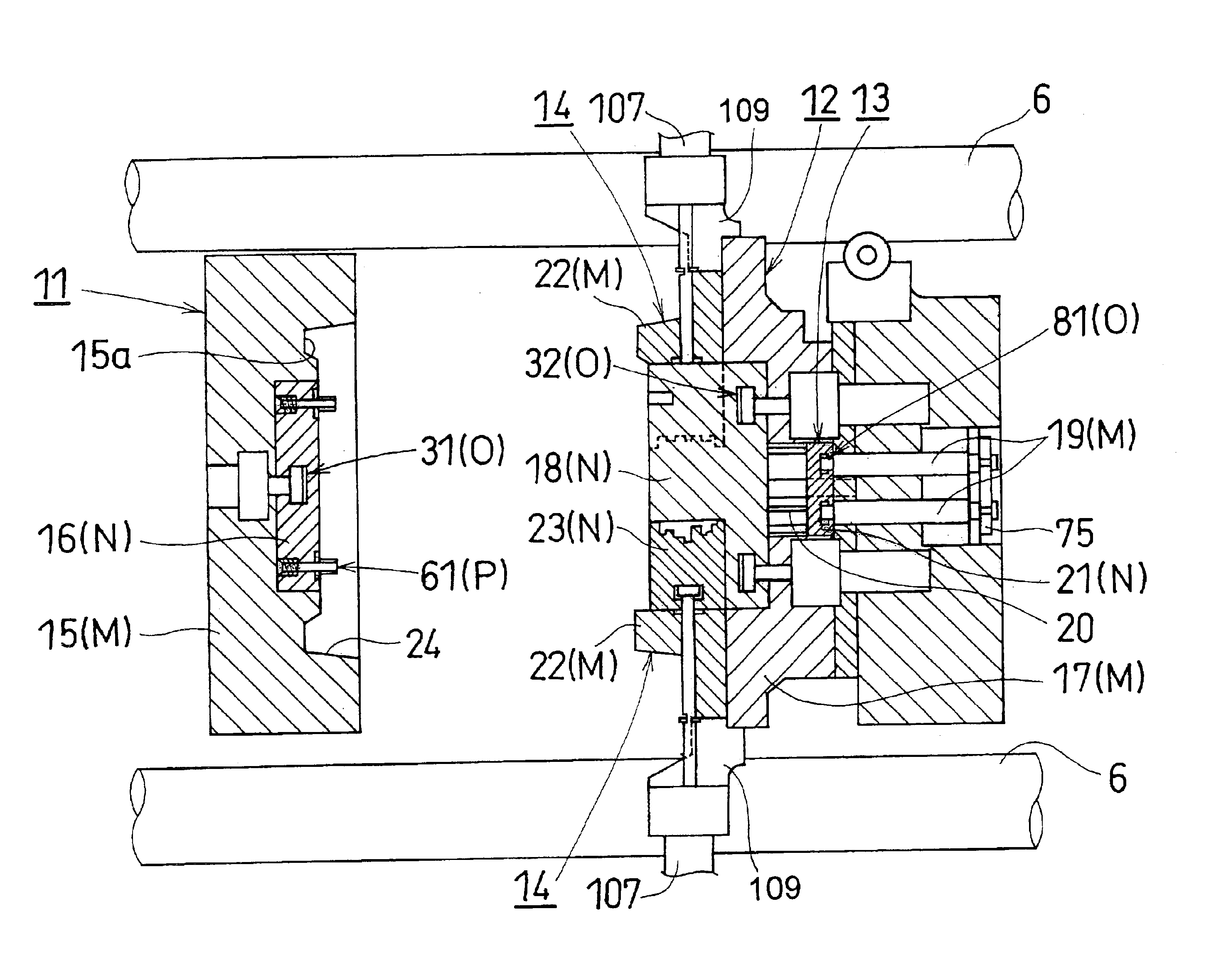
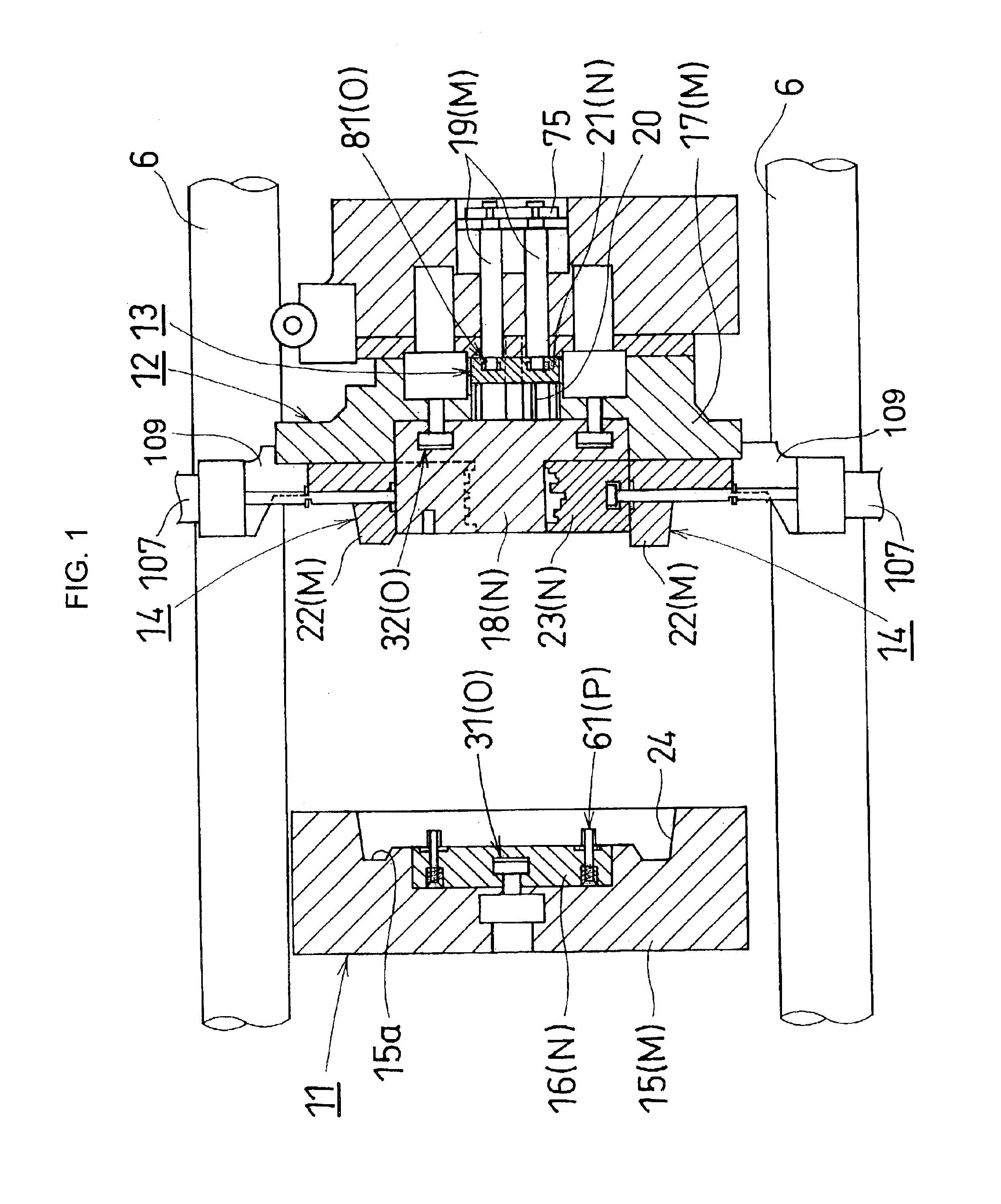
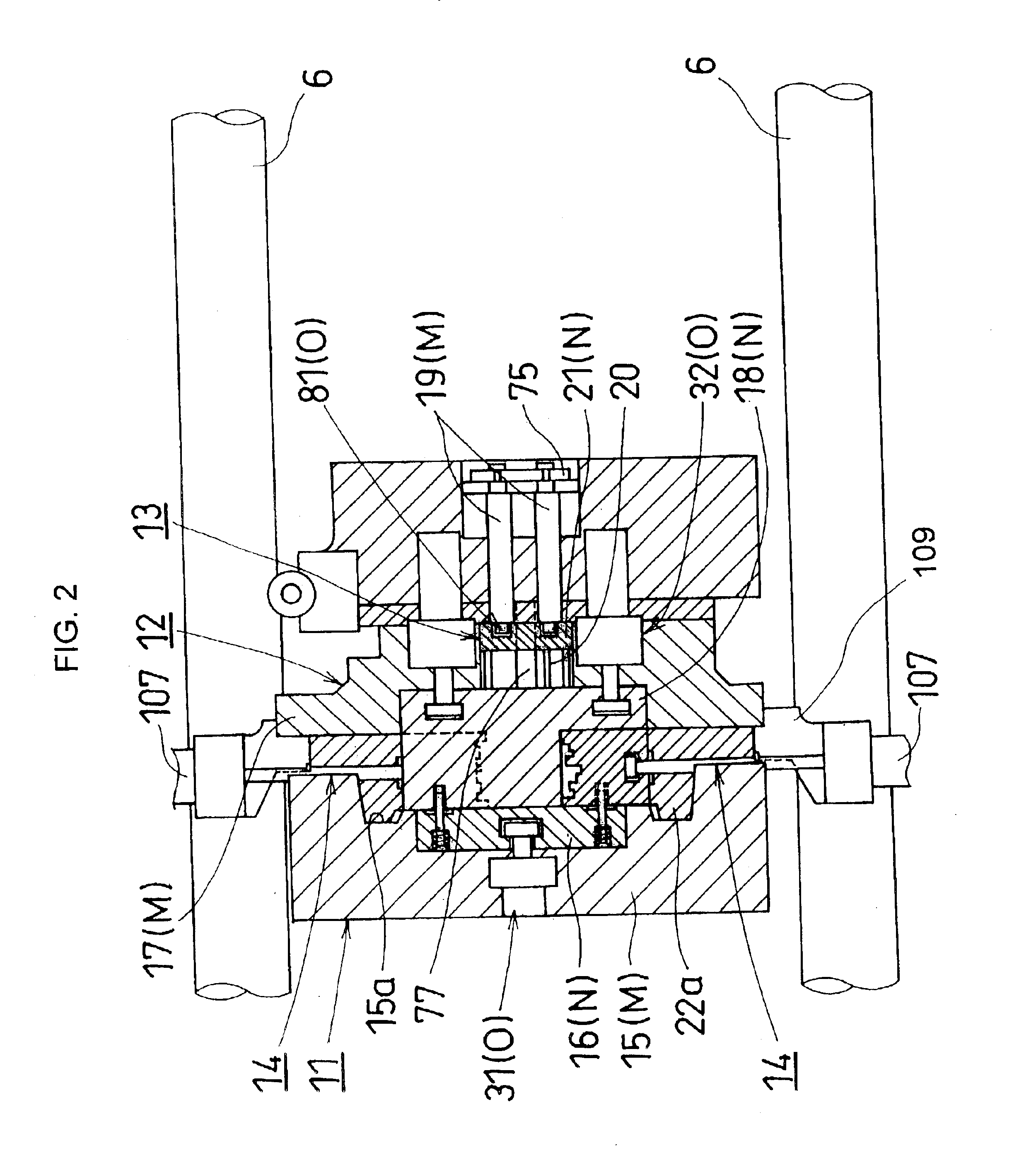
[0070]FIGS. 1 to 4 show an overall structure of a molding die corresponding to one embodiment in accordance with the present invention. The embodiment is structured as a die casting die which is provided in a horizontal die casting machine (molding machine), and is generally constituted by a fixed die 11 mounted to a fixed platen 2 of a die casting machine (hereinafter, simply referred to as a machine) 1 shown in FIG. 5, a movable die 12 mounted to a movable platen 3 of the machine 1, and pressing means 13 and a plurality of (four) slides 14 that are attached to the movable die 12. The movable platen 3 of the machine 1 is slidably supported to four tie bars 6 which are bridged between the fixed platen 2 arranged at one end portion on a stand 4 and a fixed table 5 arranged at the other end portion on the stand 4. Further, the movable platen 3 is ...


PUM

PropertyMeasurementUnit
Pressureaaaaaaaaaa
Hardnessaaaaaaaaaa

Abstract

The invention provides a molding die in which a whole or a part of an exclusive portion forming a cavity can be swiftly changed while leaving a general portion in a molding machine. A fixed insert, a movable insert, a pressing plate and a slide core which correspond to an exclusive portion can be automatically attached to and detached from a fixed main die, a movable main die, a pressing rod and a slide holder which correspond to a general portion by an attaching and detaching mechanism. Further, the fixed insert, the movable insert, the pressing plate and the slide core can be integrated in a die close state by a connection mechanism. By utilizing cross-feed means of a die changing apparatus and a die opening and closing motion on a molding machine side, the exclusive portion is automatically removed from the general portion in a form of an assembly, and the exclusive portion assembly which is transferred into the molding machine from outside the molding machine is automatically mounted to the general portion.

Description

BACKGROUND OF THE INVENTION[0001]1. Field of the Invention[0002]The present invention relates to a molding die which is used for an injection molding, a blow molding and the like in addition to various kinds of casting such as a die casting, a low pressure die casting, a gravity casting and the like, and a die changing method of the same.[0003]2. Description of the Related Art[0004]In a recent production line, a large item small scale production is generalized, and a cycle for replacing a die has become significantly short. Further, a product formed by the casting, the injection molding or the like is becoming more complex or larger in size, which makes it impossible to avoid shortening of a service life of the die, thereby increasing a frequency of replacement. In particular, in the die casting, since a high temperature molten metal is charged within the die at a high speed and a high pressure, the die is seriously damaged, thus requiring highly frequent replacement of the die.[000...

Claims


Application Information

Patent Timeline
IPC IPC(8): B22D17/22B29C33/30B29C49/48B29C45/17B29C49/42B29C35/00B29C35/16
CPCB22D17/22B22D17/229B29C33/306B29C45/1756B29C45/2675B29C49/42B29C49/4823B29C2035/1616B29C2049/4825B29C2049/4856
Inventor MATSUURA, YOSHIKIKATO, TSUKASASUZUKI, IKUOHAMADA, YUKIOKONDO, MASAKATSUFUNAHASHI, TORUMATSUNAGA, KAZUYASUKESADA, HIDEAKI
Owner TOYOTA JIDOSHA KK
Why Eureka
Try Eureka