Cable and apparatus interface security device

a security device and cable technology, applied in the direction of cable junctions, securing/insulating coupling contact members, cable connections, etc., can solve the problems of affecting the sealing system of the sealing system using gel near the maximum specified temperature, the sealing composition of the gel is typically limited, and the electrical interconnection is subject to degradation

Active Publication Date: 2005-10-18
COMMSCOPE TECH LLC
View PDF31 Cites 46 Cited by
  • Summary
  • Abstract
  • Description
  • Claims
  • Application Information

AI Technical Summary

Problems solved by technology

Electrical interconnections are subject to degradation from environmental factors such as moisture, vibration and repeated expansion and contraction from daily temperature changes.
However, gel sealing compositions are typically limited to environments where the temperature will be 60 degrees Celsius or less.
Also, in the frequently vertical configuration of a cable to antenna attachment, a sealing system using gel near the maximum specified temperature may become compromised due to gel migration and or leakage.
The prior enclosures typically use multiple hook into slot closure configurations which, once closed, may be difficult to open, especially when installed in exposed locations such as atop radio towers.
Gel seals are typically not reusable and or have only a limited number of re-uses before they must be replaced.
Vibration may

Method used


Image

  • Cable and apparatus interface security device
  • Cable and apparatus interface security device
  • Cable and apparatus interface security device

Examples


first embodiment

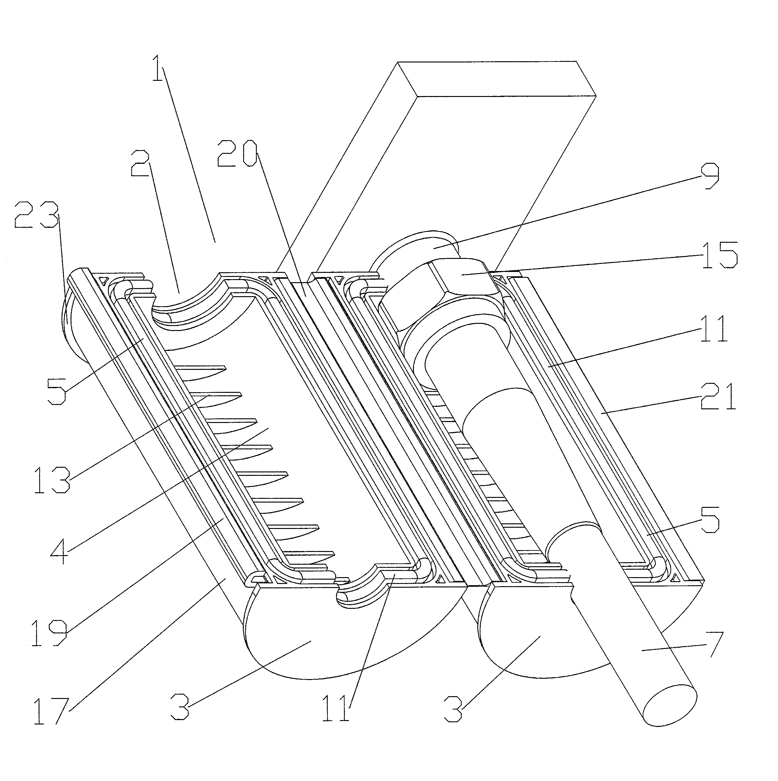
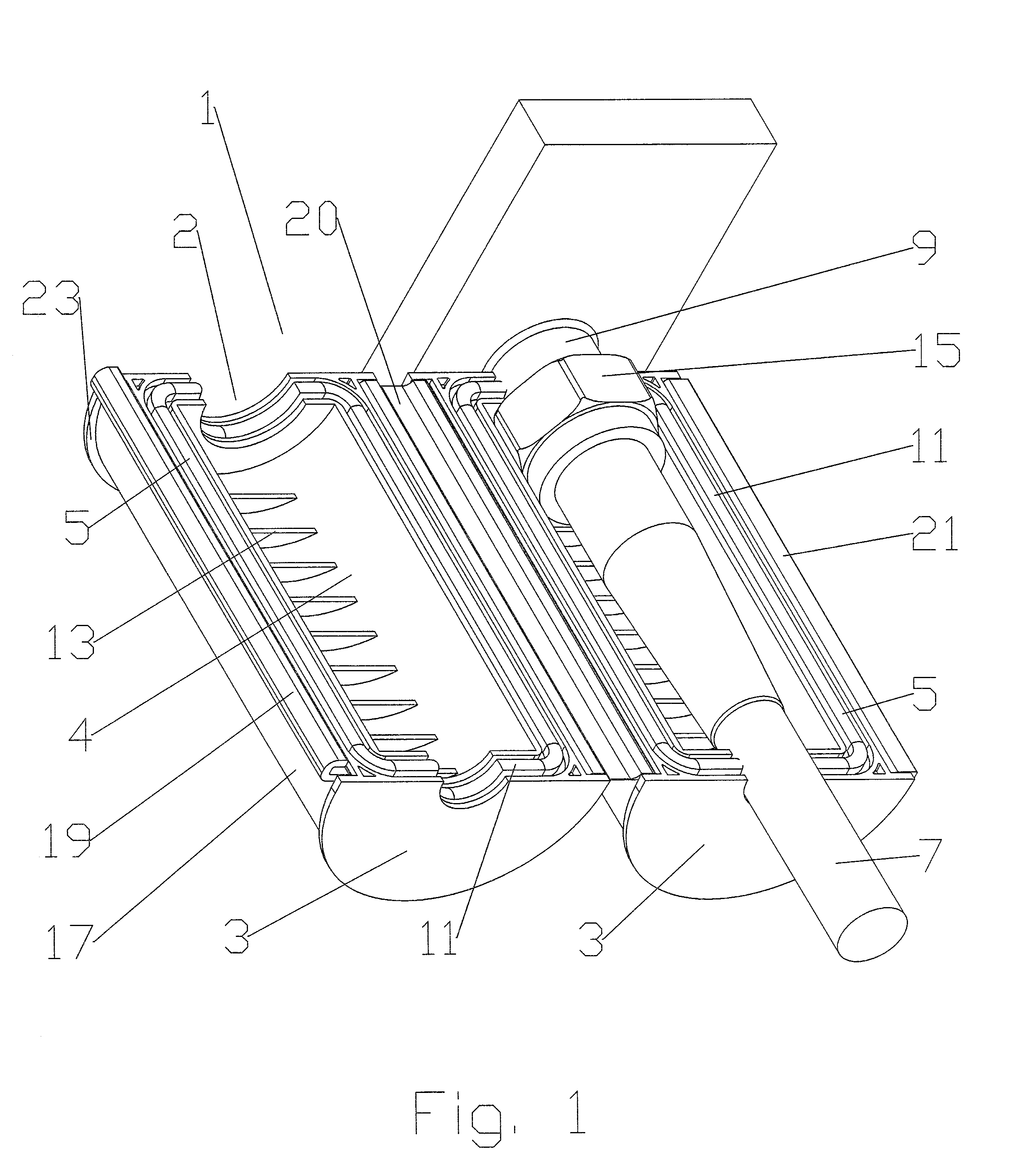
[0024]As shown for example by FIGS. 1–6, a sealing assembly 1 according to the invention has internal shell 3 halves adapted to seal against each other and around a desired interconnection space 4. The shell 3 halves may be formed, for example, from an impact resistant plastic using injection molding.

[0025]The mating surface(s) 5 of the shell 3 halves are adapted to mate with each other and around opening(s) 2 formed between the shell(s) 3 dimensioned to accept the outer diameter of the cable 7 and or apparatus connector body 9 at a cable end 6 and an apparatus end 8, respectively.

[0026]A gasket 11 lines each mating surface 5 to seal the interconnection of each shell 3 half with the other and around the outer diameter of the cable 7 and the apparatus connector body 9. The gasket 11 may be formed from, for example, liquid injection molded / liquid silicone rubber, thermoplastic elastomers, molded closed-cell foam or the like having suitable sealing and environmental resistance and stab...

second embodiment

[0033]Because the shell 3 wedges section the circumference of the sealing assembly 1 into thirds, the opportunity for pinching of the gasket(s) 11 during closure is reduced. The locking band may be omitted because when closed, the shell 3 wedge geometry of the second embodiment improves equalization of the pressure between adjacent gasket 11 surfaces and inwards towards the cable 7 and apparatus connector body 9. To form an improved seal at the junction between each adjacent gasket 11 and the cable 7 or apparatus connector body 9, protruding compensation spike(s) 37 as shown for example in FIG. 10 may be formed in the gasket 11. The increased gasket material added via the compensation spike(s) 37 increases the sealing pressure between the gasket(s) 11 and also against the cable 7 or connector body 9.

[0034]As demonstrated in the second embodiment, the gasket(s) 11 may be adapted to have increased contact area via an increased width along the longitudinal axis of the cable 7 to improv...


PUM


Abstract

A sealing assembly for a cable to apparatus interconnection formed bya plurality of shells adapted to mate together, surrounding the interconnection within an interconnection space. When mated together, the shells forming openings for the cable and the apparatus at an apparatus end and a cable end, respectively. A gasket mounted to each shell along a mating surface between the shells and along the openings environmentally seals the interconnection space. A locking rib projecting inward from the shell(s) may be applied to rotationally interlock a coupling nut of the interconnection with the sealing assembly. In a two shell embodiment, a locking band positioned around an outer diameter of the mated together shells with an end to end retaining means may be used to secure the shells together. Alternatively, if three shells are used, the shells may be hinged together and a retaining means applied to join the unhinged ends together.

Description

BACKGROUND OF INVENTION[0001]1. Field of the Invention[0002]The invention relates to a device for environmentally sealing and securing the interconnection between cables and or apparatus, for example feed and or control cables interconnected with an antenna.[0003]2. Description of Related Art[0004]Electrical interconnections are subject to degradation from environmental factors such as moisture, vibration and repeated expansion and contraction from daily temperature changes.[0005]Environmental seals such as an outer sealing enclosure that surrounds an electrical interconnection have been used, for example, to surround a cable end connector to cable end connector interconnection. The, for example, injection molded plastic enclosures have been configured to surround the cable interconnection with two halves in a clamshell hinged configuration that is sealed with a gel composition at cable exit points proximate either end. Alternatively, the enclosure may be entirely filled with a gel ...

Claims


Application Information

Patent Timeline
IPC IPC(8): H02G15/00H02G15/18H02G15/013
CPCH02G15/013H02G15/18H01R4/70
Inventor LOW, DAVIDCOX, ALBERTCRAWFORD, TIMKORCZAK, RICHARDHORVATH, RAYMOND
Owner COMMSCOPE TECH LLC
Why Eureka
Try Eureka