RJ type modular connector for coaxial cables

a technology of modular connectors and coaxial cables, applied in the direction of coupling devices, two-part coupling devices, electrical apparatus, etc., can solve the problems of difficult alignment and threaded mate of screw-on type connectors, increased time consumption, and impaired signals being transmitted over coaxial cables. to achieve the effect of reducing the diameter of the outer sleev

Inactive Publication Date: 2005-10-18
CROAN QUINN F
View PDF11 Cites 53 Cited by
  • Summary
  • Abstract
  • Description
  • Claims
  • Application Information

AI Technical Summary

Benefits of technology

[0014]In preferred and modified forms of the invention, one or more ribs or sealing rings are provided adjacent to the entrance end of the outer sleeve, each rib having an inner rounded surface deformable into a portion of the jacket until the jacket occupies a circumferentially extending space between each adjacent pair of the ribs, and the inner sleeve has external projections along an external wall surface of the inner sleeve adjacent to the one end. The outer sleeve when crimped with a crimping tool wil...

Problems solved by technology

A problem with the screw-on type coaxial connector is that the relative inflexible coaxial cable makes the screw-on type connector difficult to align and threadedly mate together.
The push-on type connector also has a tendency to evolve a lower quality of electrical connection over time with the result that signals ...

Method used


Image

  • RJ type modular connector for coaxial cables
  • RJ type modular connector for coaxial cables
  • RJ type modular connector for coaxial cables

Examples


Embodiment Construction

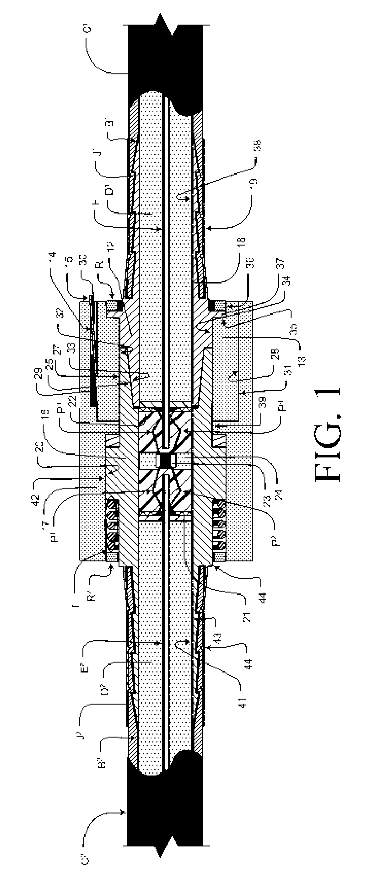
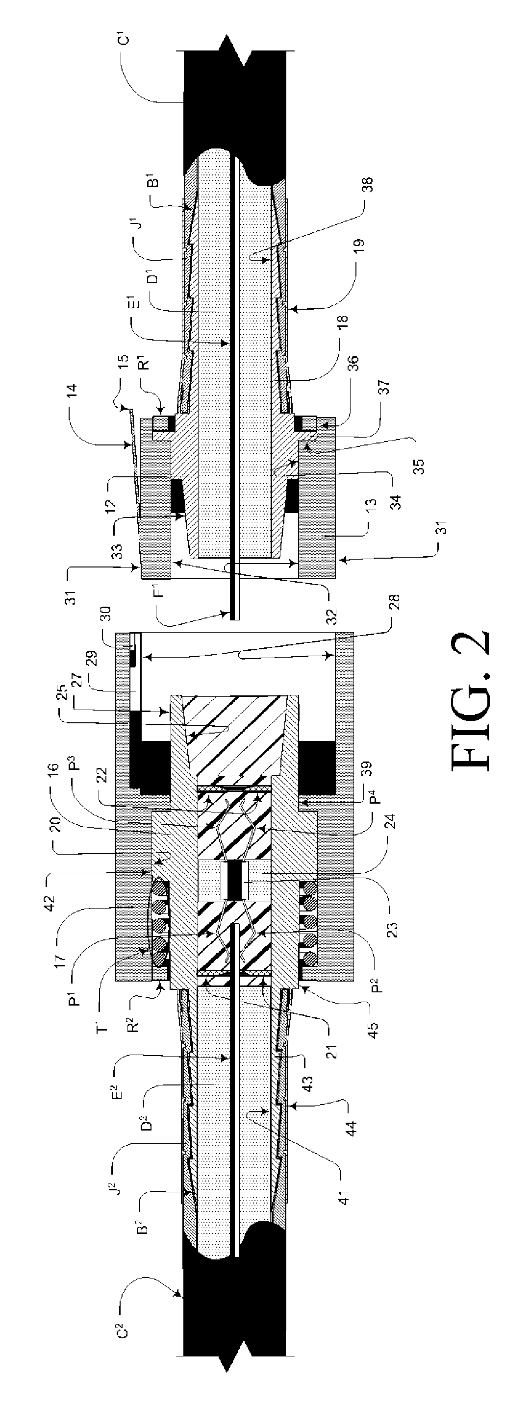
[0035]Referring in more detail to the drawings, there is shown by way of illustrative example in FIGS. 1, 2, 3, 4, 4a, 4b, 5, 5a and 5b a plug assembly 10 and socket assembly 11 for positively interconnecting conventional forms of coaxial cables C1 and C2. As a setting for the present invention, inner and outer sleeves, 18 and 19 of plug assembly 10, and 43 and 44 of socket assembly 11, are of a type employed in existing screw type and push type connectors, and form the components of said connectors that capture a coaxial cable in the connector. These are shown in preferred and modified forms of the invention as only one viable method of directly connecting the novel portions of the invention directly to a cable, which, by providing for direct connection to the plug assembly and / or socket assembly, is, in and of itself, a novel element of the current invention.

[0036]The plug assembly 10 is broadly comprised of a plug body 13, having a locking tab 14 with release tab 15, with bore 32...


PUM


Abstract

A connector employing a plug assembly and socket assembly for coaxial cables having apertures, conductive elements, mating surfaces and locking mechanisms to maintain the electrical characteristics of the cable joined to the plug and socket, to hold the plug and socket physically in connection with one another, and to establish and maintain the electrical characteristics of the cables through the connector. The plug is configured to attach to a coaxial cable in such a manner that: a) the center conductor of the coaxial cable extends through the plug assembly for engagement with mating conductors in the socket, and b) such that the shield of the cable is physically and electrically engaged by a conductive element extending through the plug which contacts the conductive elements within the socket. These two features establish electrical contact of the shield and center conductor into and through the connector. The connector includes a socket assembly having a receiving aperture formed therein for receiving the plug assembly. The socket assembly is configured to accept a second coaxial cable for electrically contacting the first coaxial cable when the plug is received in the receiving aperture, or, in the modified form, for connecting the first coaxial cable to terminal equipment. The socket assembly includes an outer conductor element that is electrically isolated from inner conductive elements of the socket assembly which provide electrical continuity for the inner conductor of the cables. The outer conductor and inner conductor of the plug assembly and socket assembly are electrically connected when the plug is received in the receiving aperture. The plug and socket assemblies incorporate a snap-fit, locking mechanism to retain the plug and socket assemblies in mechanical and electrical connection with each other.

Description

BACKGROUND OF THE INVENTION[0001]This invention relates to fittings for connecting coaxial cables together and to terminal devices, and relates to a novel and improved end connector for establishing and maintaining a mechanical and electrical connection through the use of a modular arrangement that incorporates a locking mechanism.[0002]Coaxial cables are generally characterized by being made up of inner and outer concentric conductors (or center conductor and shield respectively) separated by a dielectric insulator and encased or covered by a protective outer jacket of rubber or rubber-like material. Numerous types of end connectors have been devised to effect a secure mechanical and electrical connection to the end of the coaxial cable and in such a way that the inner conductor and dielectric insulator extend through an inner sleeve of the connector while the outer conductor and jacket are inserted into an annular space between the inner sleeve and an outer concentric sleeve. The ...

Claims


Application Information

Patent Timeline
IPC IPC(8): H01R9/05H01R13/627H01R13/646
CPCH01R13/6272H01R24/40H01R24/44H01R24/564H01R13/5837H01R2103/00
Inventor CROAN, QUINN F.
Owner CROAN QUINN F
Why Eureka
Try Eureka