Porous dike intake structure for fish diversion

a technology of intake structure and porous dike, which is applied in the field of fish diversion, can solve the problems of no means of preventing attachment, no means of reducing fish passages, and no patents on porous dike or breakwaters teach the concept of porous dike or the means of excluding fish using small passages through the intake structur

Inactive Publication Date: 2005-10-18
KINECTRICS
View PDF17 Cites 21 Cited by
  • Summary
  • Abstract
  • Description
  • Claims
  • Application Information

AI Technical Summary

Benefits of technology

[0006]It is an object of the present invention to provide a means of diverting fish and other aquatic life a

Problems solved by technology

None of these inventions teach a porous dike concept or means of excluding fish using small passages through the intake structure.
There are also no means of preventing attachment due to mollusks such as zebra mussels or related species through these passages.
Similarly, patents on porous dikes or breakwaters do not teach means of reducing fish passage or ways of preventing attachment from zebra mussels and rel

Method used


Image

  • Porous dike intake structure for fish diversion
  • Porous dike intake structure for fish diversion
  • Porous dike intake structure for fish diversion

Examples


Embodiment Construction

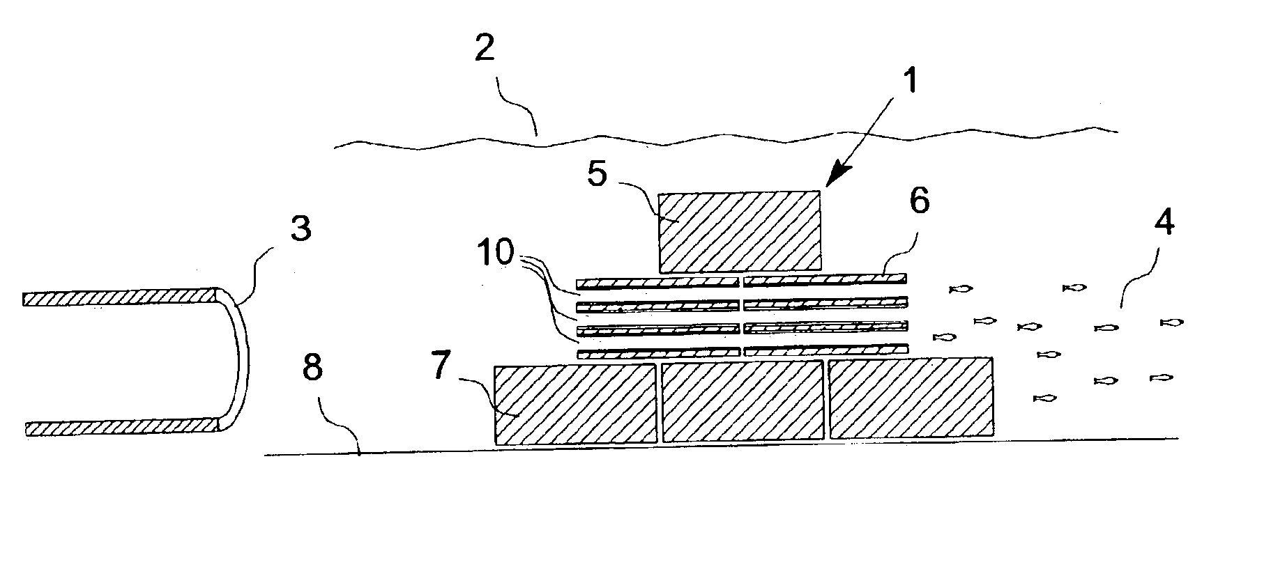
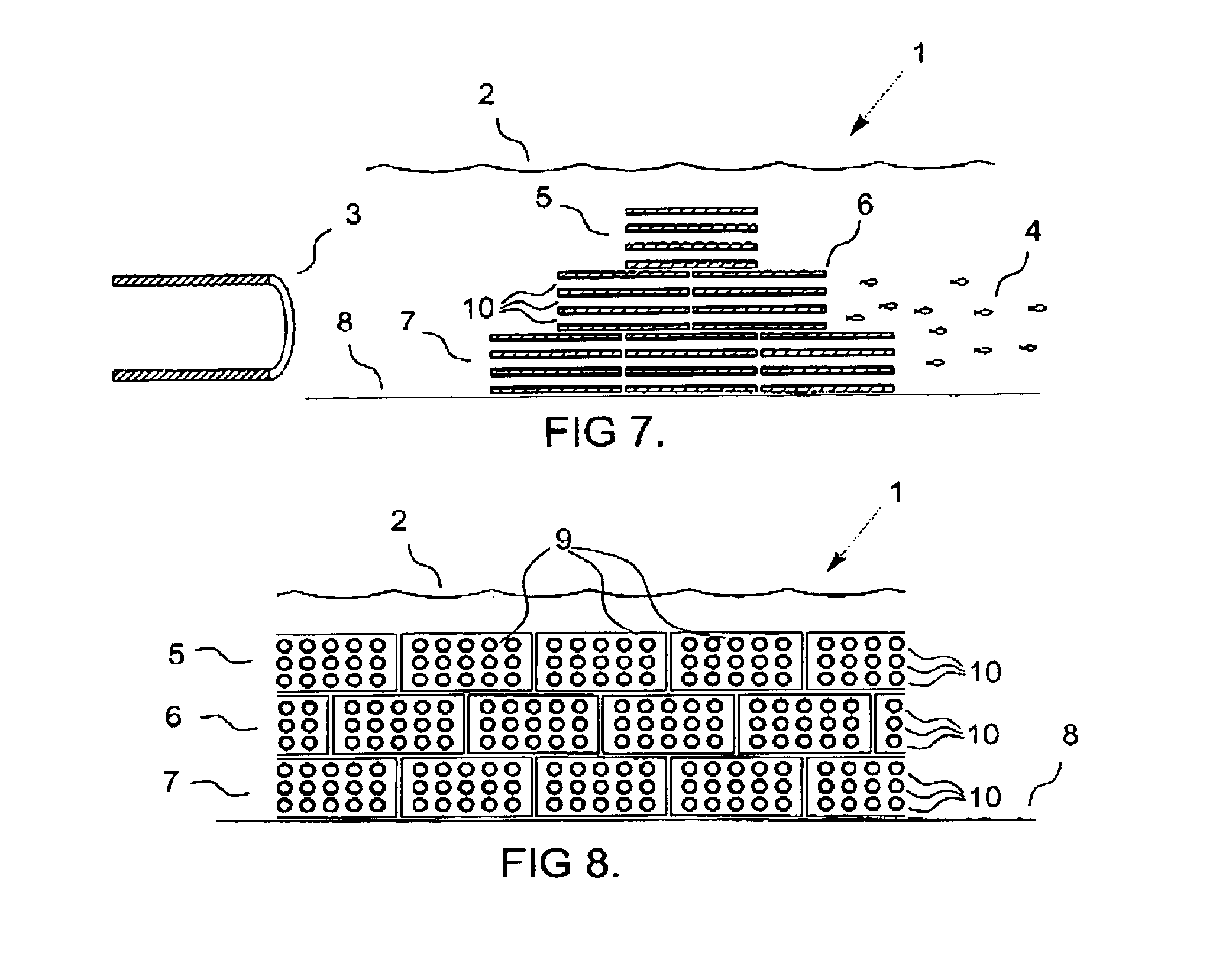
[0017]A preferred embodiment of the present invention will now be described with reference to the drawings. Referring now to FIG. 1, a water intake 3 collects water which must flow either over or through submerged dike 1 of the invention. The dike 1 of the invention, in one preferred embodiment, comprises a top portion 5 below the water surface 2, a central portion 6, and a bottom portion 7 which rests on the bottom 8 of the lake or other body of water. The fish 4 are kept away from water intake 3 by the dike 1.

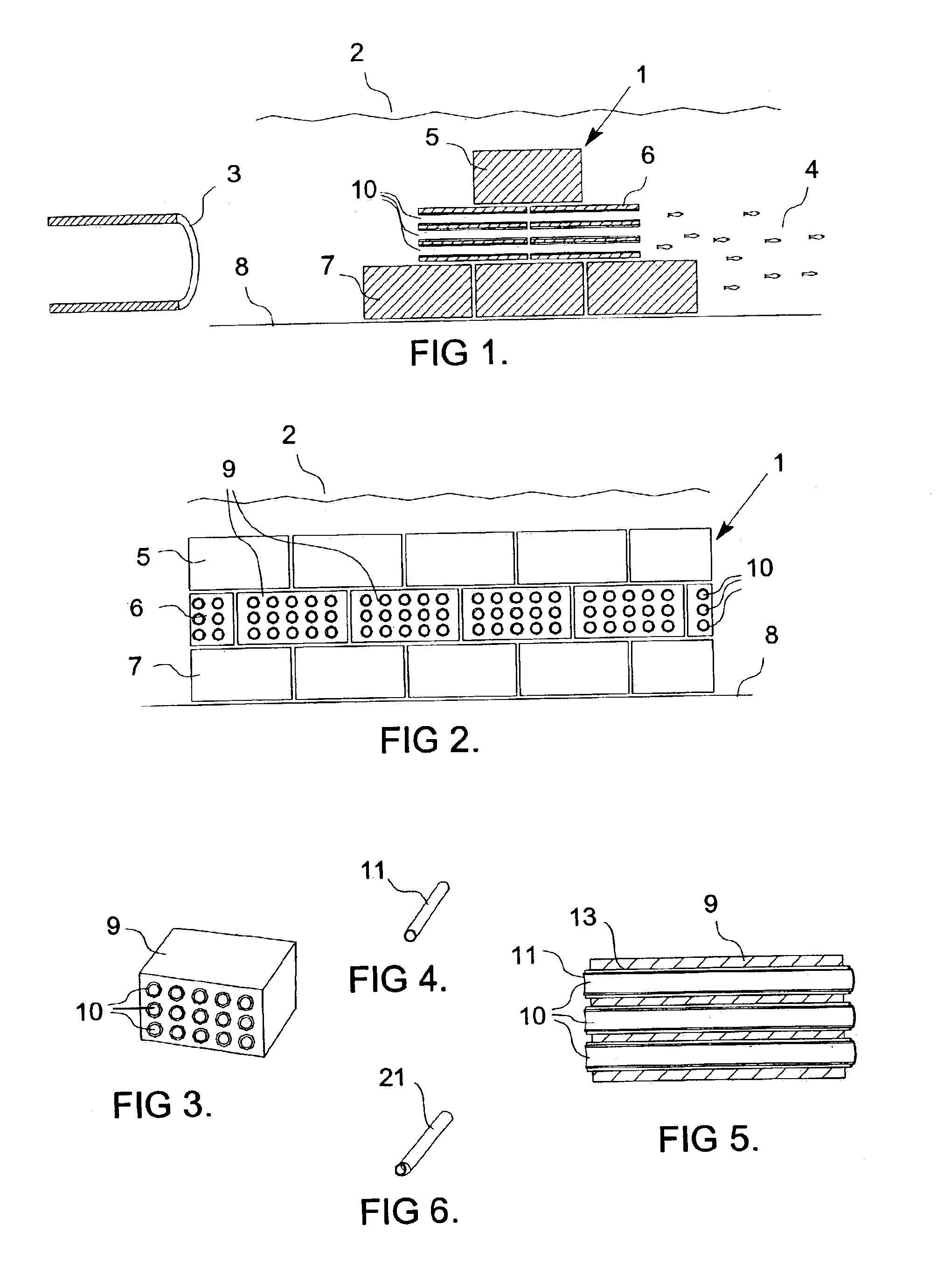
[0018]Referring now to FIG. 2, a cross-section of the porous dike 1 is shown. The bottom portion 7 comprises water-impermeable, preferably solid, blocks; the central portion 6 comprises blocks 9 with flow passages 10, and the top portion 5 comprises generally opaque blocks which will appear to a fish as an obstruction. Preferably the blocks in the top portion 5 are solid, for ease of manufacture and stability in the dike 1. The upper limit of the top portion 5 is preferably d...


PUM

PropertyMeasurementUnit
Angleaaaaaaaaaa
Widthaaaaaaaaaa
Widthaaaaaaaaaa

Abstract

A structure for diverting fish away from water intakes comprises a porous dike having a bottom portion, a central portion, and a top portion, the top portion preferably being submerged a short distance below the surface, and the central portion having flow passages. In a preferred embodiment, the top and bottom portions comprise solid blocks and the flow passages in the central portion are lined with zebra mussel resistant sleeves to minimize clogging. Preferably the sleeve can be readily replaced as desired.

Description

FIELD OF THE INVENTION[0001]This invention relates to fish diversion from water intakes of dams, power plants and other industrial systems requiring large quantities of water. This invention also relates to the prevention of clogging by zebra mussels or related biofouling organisms.BACKGROUND OF THE INVENTION[0002]In the prior art there are disclosed numerous systems for diverting fish and other aquatic life from water intakes. Most of these systems deal with different intake designs. U.S. Pat. No. 4,064,048 issued Dec. 20, 1977 to Downs et al., which is incorporated herein by reference, teaches the use of louvers, U.S. Pat. No. 6,051,131 issued Apr. 18, 2000 to Maxson, which is incorporated herein by reference, teaches the use of submerged intake screens, U.S. Pat. No. 5,385,428 issued Jan. 31, 1995 to Taft, 3rd et al., which is incorporated herein by reference, teaches the use of a plane screen, U.S. Pat. No. 4,415,462 issued Nov. 15, 1983 to Finch, et al., which is incorporated h...

Claims


Application Information

Patent Timeline
IPC IPC(8): A01K61/00A01K79/00A01K79/02E02B1/00
CPCA01K61/00A01K79/02E02B1/006Y10S210/931Y02A40/60Y02A40/81
Inventor PATRICK, PAUL H.KOWALYK, HENRY E.HERRMANN, OTTO
Owner KINECTRICS
Why Eureka
Try Eureka