System and method for high-performance scanner calibration

a scanning system and high-performance technology, applied in the field of scanning system calibration, can solve the problems of noticeably speeding up scan and copy time, and achieve the effects of reducing the memory requirement for offset and gain calibration, reducing the size/performance bottleneck of the scanner system, and increasing performan

Inactive Publication Date: 2006-01-05
JOHN V PEZDEK
View PDF28 Cites 20 Cited by
  • Summary
  • Abstract
  • Description
  • Claims
  • Application Information

AI Technical Summary

Benefits of technology

[0010] The present invention is directed to a system and method for reducing the memory requirement for offset and gain calibration to relieve the size/performance bottleneck in scanner systems. The resulting me

Problems solved by technology

Since the calibration step is often the bottleneck in scanner p

Method used


Image

  • System and method for high-performance scanner calibration
  • System and method for high-performance scanner calibration
  • System and method for high-performance scanner calibration

Examples


Embodiment Construction

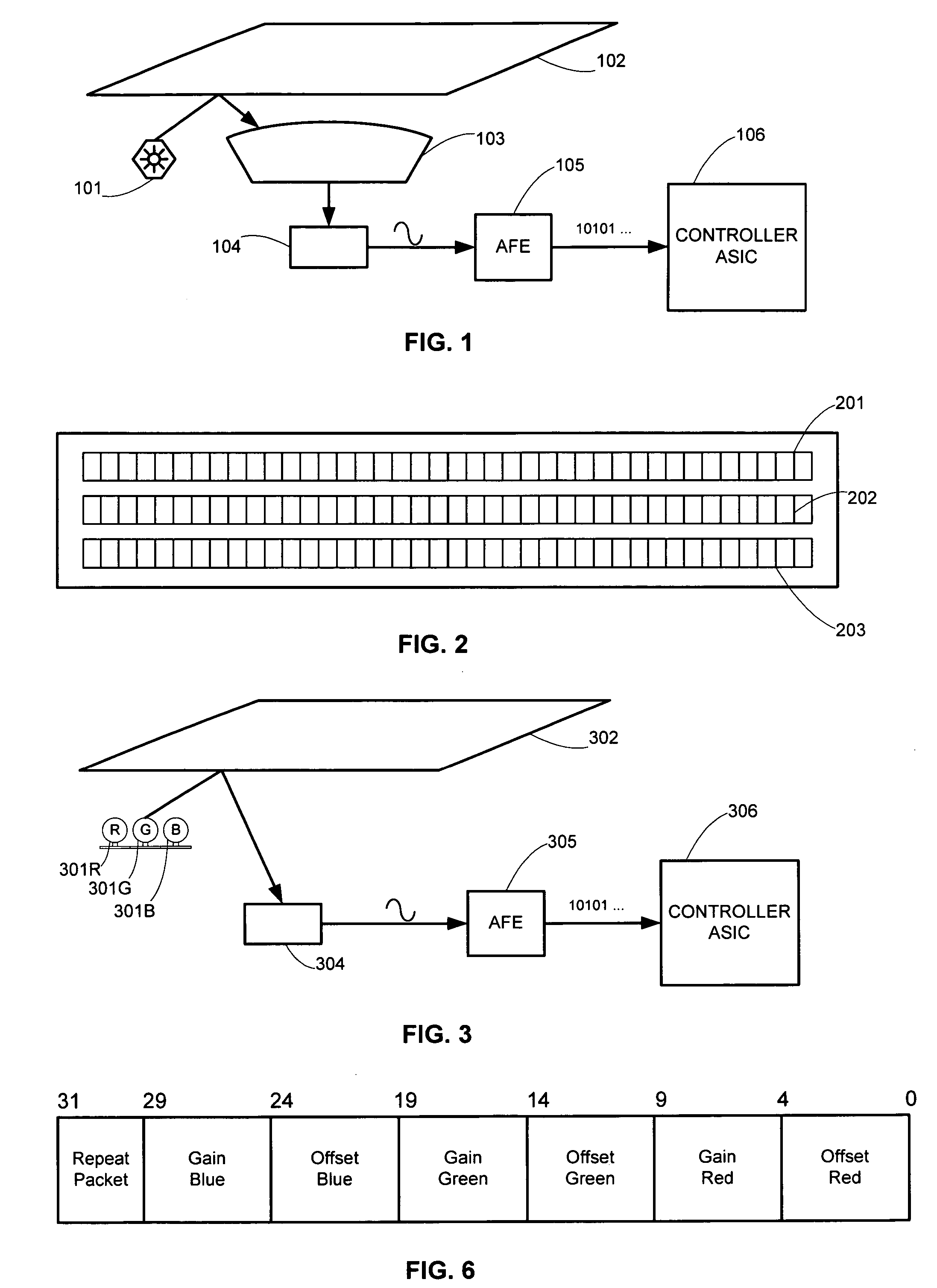
[0021]FIG. 1 shows a basic block diagram for an optical reduction scanner (which is often incorrectly labeled a CCD scanner). Charge coupled device (CCD) elements refer to the technology of the image sensor, in one embodiment. CCD image sensors have historically been used with optical reduction scanners, hence the confusion. The following is an explanation of the basic operation of this type of scanner. Of course, it will be readily understood that the present invention may be used with a wide variety of scanners.

[0022] A white light source 101 such as a fluorescent bulb is used to illuminate a line of the target image 102. This type of light source contains the red, green, and blue wavelengths of light. The light reflects off of the target image and is directed through a series of optical elements 103 that shrink the image down to the size of the small image sensor 104.

[0023] The image sensor 104 typically contains three rows of elements. As shown in FIG. 2, each row (201, 202 an...


PUM


Abstract

The present invention is directed to a system and method for reducing the memory requirement for offset and gain calibration to relieve the size/performance bottleneck in scanner systems. The resulting methodology produces visually equivalent scanned results with a substantial increase in performance, which results in a shorter amount of time required to output a first copy in, for example, an all-in-one device. Since the calibration step is often the bottleneck in scanner performance, this method noticeably speeds up scan and copy time. Implementing the decompression in hardware requires a minimal amount of hardware overhead and complexity. Thus, this method has a minimal impact on the size and cost of the scanner controller (e.g., an ASIC—application specific integrated circuit). Since compression only takes place at most once per scan, this added step has no significant impact on the overall scan time. By allowing dynamic grouping of pixels using a single calibration packet, the quality of the compensation can be optimized with the size of the compensation data being minimized. Adding the ability to shift the compressed deviation stored in the calibration packet, the range of the pixel-to-pixel deviation can be increased without impacting the size of the calibration data. This flexibility makes this invention applicable to future image sensors that may have widely varying deviations in pixel-to-pixel offset and gain values.

Description

CROSS REFERENCES TO RELATED APPLICATIONS [0001] None. STATEMENT REGARDING FEDERALLY SPONSORED RESEARCH OR DEVELOPMENT [0002] None. REFERENCE TO SEQUENTIAL LISTING, ETC. [0003] None. BACKGROUND OF THE INVENTION [0004] 1. Field of the Invention [0005] The present invention generally relates to the calibration of scanning systems, such as those found in host-based scanners, all-in-one (AIO) devices, and the like. [0006] 2. Description of the Related Art [0007] When scanning an image using a host-based scanner or multi-functional device such as an all-in-one (AIO), it is necessary to compensate for imperfections in the scanning system in order to accurately reproduce the target image. Two characteristics of CCD based image sensors contained in scanners that require such compensation are dark signal non-uniformity (DSNU) and photo response non-uniformity (PRNU). DSNU refers to the pixel-to-pixel variation in a CCD array to the detected black level or zero light present level. PRNU refers...

Claims


Application Information

Patent Timeline
IPC IPC(8): H04N1/46
CPCH04N1/401H04N5/3651H04N5/361H04N25/63H04N25/671
Inventor BAILEY, JAMES R.BRESWICK, CURT P.CRUTCHFIELD, DAVID A.YACKZAN, JOSEPH K.
Owner JOHN V PEZDEK
Why Eureka
Try Eureka