Method and device for generating a laser beam, a laser treatment device and a laser detection device

a laser detection and laser treatment technology, applied in the field of laser detection devices, can solve the problem of rigid beams, and achieve the effect of increasing flexibility

Inactive Publication Date: 2010-03-18
KONINKLIJKE PHILIPS ELECTRONICS NV
View PDF8 Cites 20 Cited by
  • Summary
  • Abstract
  • Description
  • Claims
  • Application Information

AI Technical Summary

Benefits of technology

[0005]It is an object of the present invention to provide a method and device for generat

Problems solved by technology

A disadvantage of lasers and the way of generating a laser beam as

Method used


Image

  • Method and device for generating a laser beam, a laser treatment device and a laser detection device
  • Method and device for generating a laser beam, a laser treatment device and a laser detection device
  • Method and device for generating a laser beam, a laser treatment device and a laser detection device

Examples


Embodiment Construction

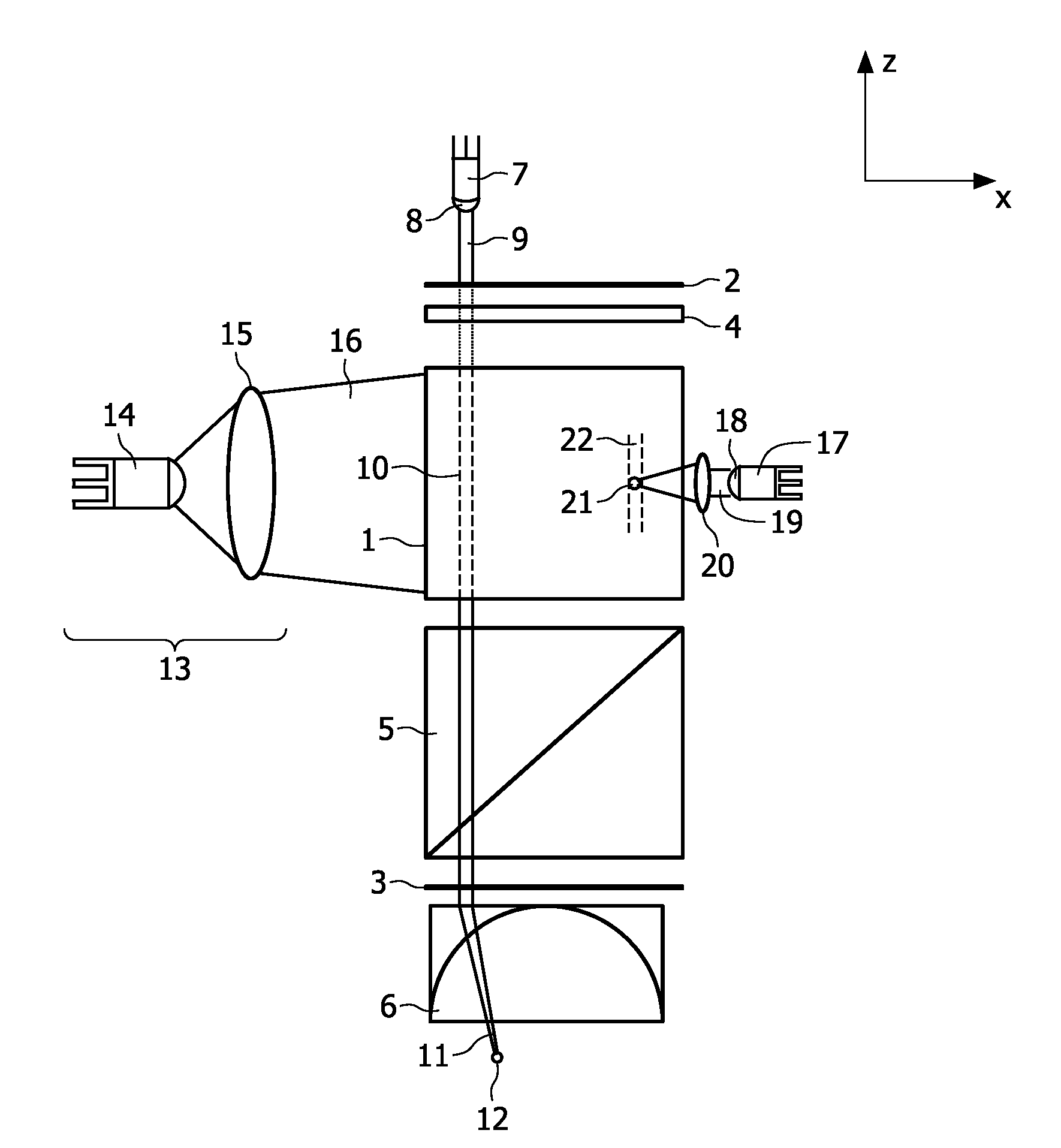
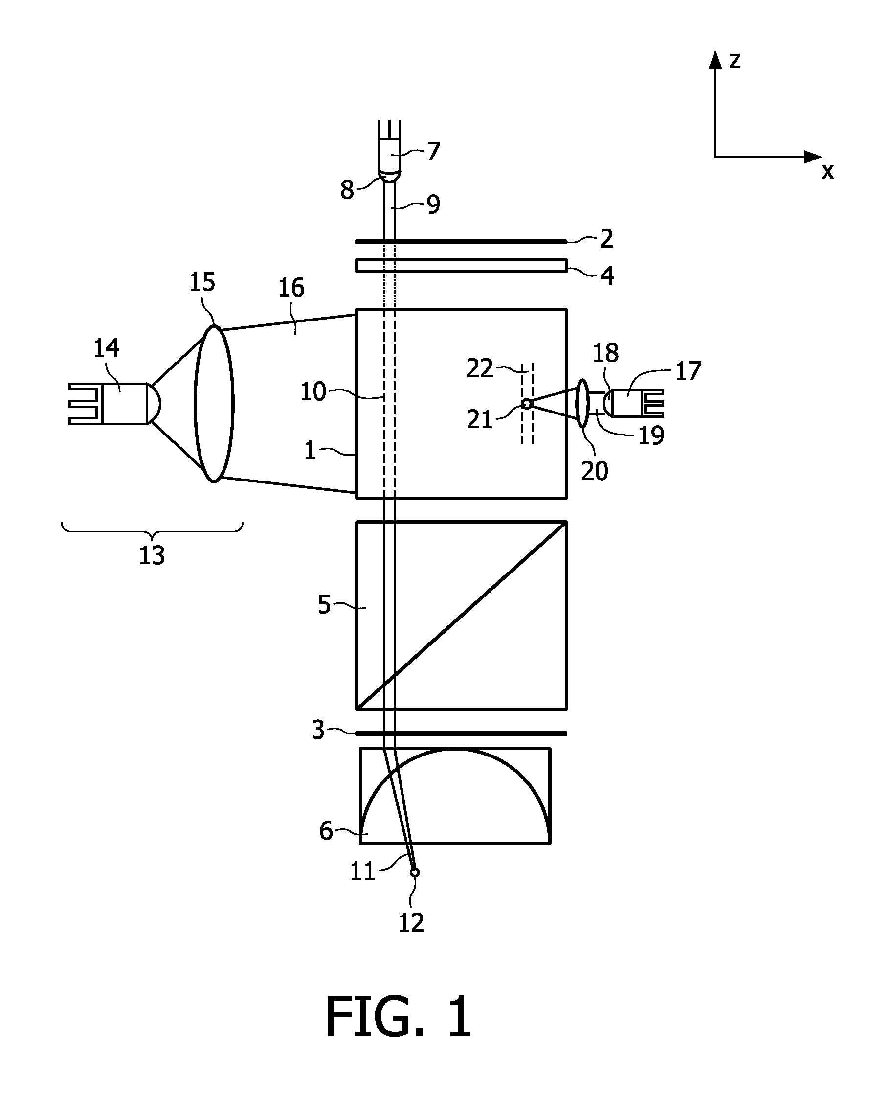
[0072]FIG. 1 very generally depicts a device that shows various inventive features.

[0073]Herein, 1 denotes a piece of laser material, in a laser cavity delimited by a first cavity mirror 2 and a second cavity mirror 3. A Q-switch is indicated by 4, and an optional polarizing beam splitter with 5. A focusing lens 6 is also optional.

[0074]A first diode 7 with a diode lens 8 emits a beam 9, which forms a laser beam 10 in the laser material 1, that is shaped to a focused beam 11 having a focal point 12.

[0075]An optical pump is indicated by 13, with a pump diode 14 and a lens 15, and emits a pump beam 16.

[0076]A diode 17 with diode lens 18, emits a beam 19 that is focused on a diode beam focal spot 21, causing a laser beam 22.

[0077]The laser material may be any material suitable for laser action with a desired wavelength. Such wavelength may e.g. be anywhere in the optical range, i.e. uv, visible or infrared. For shaving purposes, desirable wavelengths are around 800-2000, especially bet...


PUM


Abstract

The invention relates to a laser device, comprising a laser material (1) brought into a simmer mode. A controllable source (7, 17) of additional energy (16, 20) supplies energy to the laser material (1), such that in only a desired part of the laser material (1) a lasing threshold is exceeded, and a laser beam (10) is emitted from only a desired part of the laser surface. This device makes possible to provide a laser beam in just the desired part of the laser, which allows a flexible and localized output. The invention further relates to a hair-removing device comprising a laser device according to the invention and further comprising an optical system (6) for focusing the laser beam pulses on a focal spot (12) and for positioning the focal spot in a target position, wherein the optical system (6) comprises a movable lens or a plurality of individually addressable lenses.

Description

FIELD OF THE INVENTION[0001]The invention relates to a method and device for generating laser pulses.[0002]The invention also relates to a hair-removing device using such method and / or device.BACKGROUND OF THE INVENTION[0003]Methods of generating laser pulses are well-known. Very generally, they consist of bringing about a population inversion in a suitable material, such that stimulated emission may occur, and further increasing the intensity by reflecting the generated radiation between mirrors in a laser cavity. Such lasers may also be pumped and pulsed lasers, which are able to generate very short and very intense pulses of radiation.[0004]A disadvantage of lasers and the way of generating a laser beam as mentioned above is that it is rather inflexible as regards the beam. In fact, it is there or not, with at most a variable power, repetition frequency and / or frequency.OBJECT OF THE INVENTION[0005]It is an object of the present invention to provide a method and device for genera...

Claims


Application Information

Patent Timeline
IPC IPC(8): A61B18/20H01S3/11H01S3/101
CPCA61B18/20H01S3/2383A61B19/5212A61B2017/00752A61B2018/00452A61B2018/00476A61B2018/00904H01S3/005H01S3/0071H01S3/094076H01S3/0941H01S3/09415H01S3/101H01S3/1024H01S3/113A61B18/203A61B90/361
Inventor SPIKKER, BART WILLEM JANVERHAGEN, RIEKO
Owner KONINKLIJKE PHILIPS ELECTRONICS NV
Why Eureka
Try Eureka