Stator for reciprocating motor

a technology of reciprocating motors and stators, which is applied in the direction of positive displacement liquid engines, machines/engines, magnetic circuit shapes/forms/construction, etc., can solve the problems of increased production costs, long period and process, and inability to meet the needs of mass production

Inactive Publication Date: 2005-10-18
LG ELECTRONICS INC
View PDF10 Cites 17 Cited by
  • Summary
  • Abstract
  • Description
  • Claims
  • Application Information

AI Technical Summary

Benefits of technology

[0021]Therefore, it is an object of the present invention to provide a stator for a reciprocating motor which is suitable for mass product by manufacturing and assembling components in simple way, and by managing the size of that components precisely.

Problems solved by technology

Thereby, the production cost is increased, and the manufacturing period and the process becomes longer because the lamination sheet 11 is stacked by manual work, so it is not suitable for mass product.

Method used


Image

  • Stator for reciprocating motor
  • Stator for reciprocating motor
  • Stator for reciprocating motor

Examples


Embodiment Construction

[0034]Hereinafter, the stator of the reciprocating motor according to the present invention will be described with reference to the embodiments shown in the accompanying drawings.

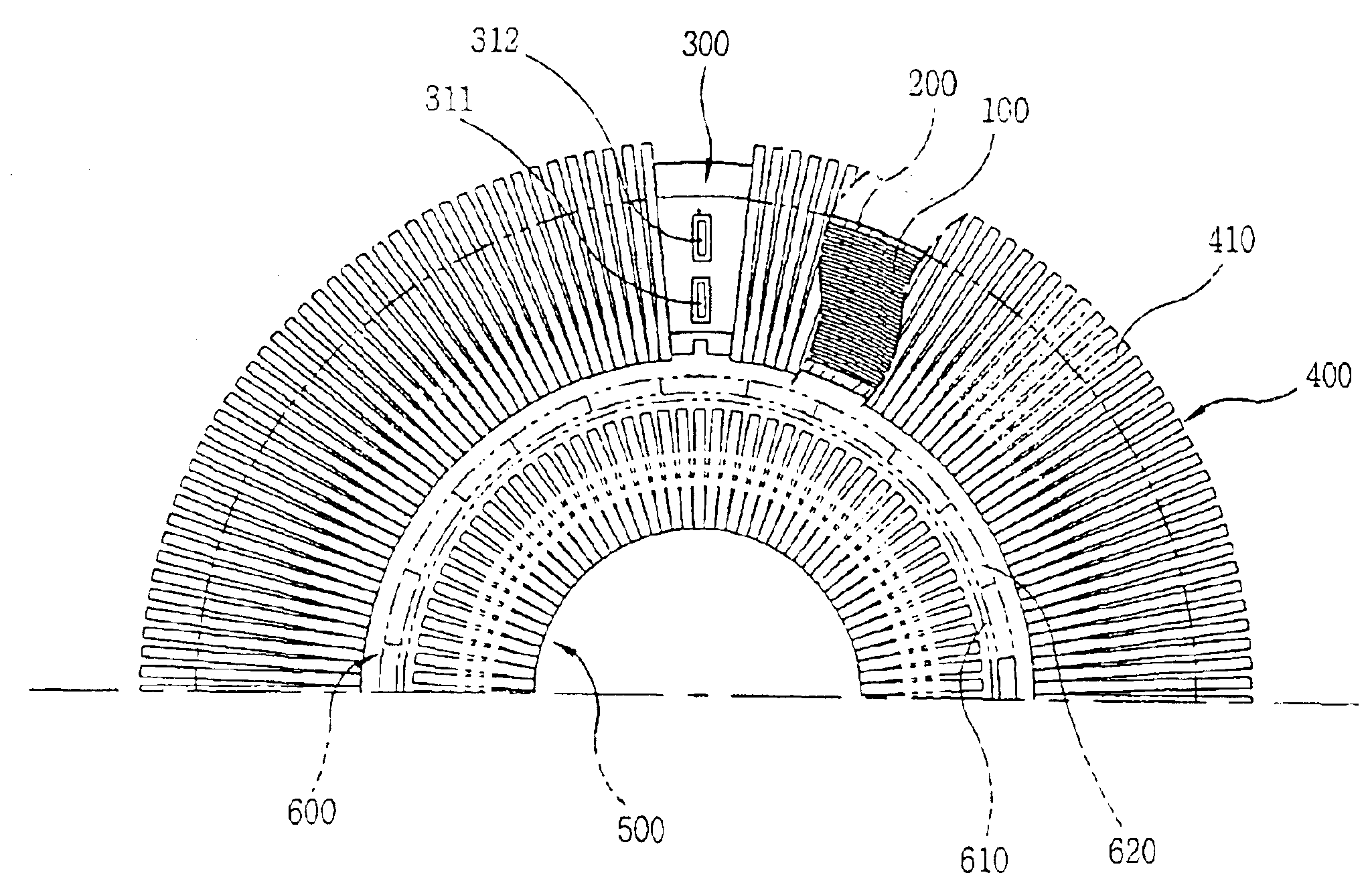
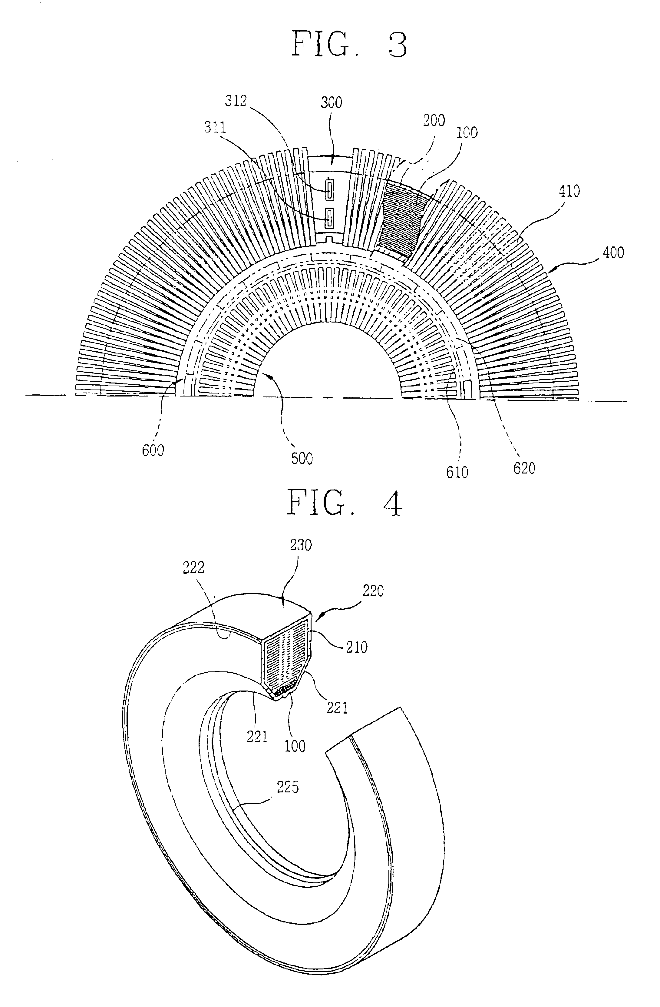
[0035]FIG. 3 shows an embodiment of the stator of the reciprocating motor according to the present invention. As shown therein, the stator of the reciprocating motor comprises a bobbin 200 made of an insulating material in which the winding coil 100 is located; a terminal unit 300 formed integrally with the bobbin 200 and connecting the winding coil 100 electrically with the outer power source; and core unit 400 formed by stacking a plurality of lamination sheets 410 along with the bobbin 200 started from one side surface of the terminal unit 300.

[0036]As shown in FIG. 4, the bobbin 200 is formed as an annular shape, and includes a bobbin body 220 having a winding recess 210 in which the coil is wound inside and a cover 230 coupled integrally with the bobbin body 220 so as to cover the winding recess 210 of...


PUM


Abstract

A stator for a reciprocating motor includes a bobbin made of an insulating material in which a winding coil is located; a terminal unit forming a single body with the bobbin and connecting the winding coil electrically with an outer power source; and a core unit stacked radially along with the bobbin started from one side of the terminal unit. Therefore, the winding coil and the bobbin can be coupled in simple way, and the core unit can be stacked simply and precisely, so the mass productivity of the motor is able to be increased. Also, the size of the core unit is able to be managed simply and precisely, and then, the contact and impact with other components constructing the motor is prevented, whereby the reliability of the motor can be improved.

Description

TECHNICAL FIELD[0001]The present invention relates to a stator for a reciprocating motor, and particularly, to a stator for reciprocating motor which is suitable for mass product by manufacturing and assembling components in simple way, and by managing the size of components precisely.BACKGROUND ART[0002]Generally, a motor is an apparatus which changes electric energy into kinetic energy, and it is classified into a rotating type motor which changes the electric energy into rotational motion and a reciprocating motor which changes the electric energy into linear reciprocating motion.[0003]The motor is used in many ways as a power source. Especially, it is installed in almost electric appliances such as refrigerator, air conditioner, washing machine, and electric fan, etc. In case of refrigerator and air conditioner, it is able to be used to rotate a blast fan, but also used as a power source by being installed on a compressor in a refrigerating cycle device constituting the refriger...

Claims


Application Information

Patent Timeline
Patent Type & Authority Patents(United States)
IPC IPC(8): H02K3/52H02K1/14H02K3/50H02K33/00H02K3/46H02K33/16F04B39/00
CPCH02K1/145H02K3/50H02K3/525H02K33/16F04B39/00
Inventor YOON, HYUNG-PYOJEON, SI-HANGDO, JIN-YEONGKIM, HYEONG-SUKPARK, KYEONG-BAE
Owner LG ELECTRONICS INC
Why Eureka
Try Eureka