High side current monitor with extended voltage range

a current monitor and voltage range technology, applied in the field of current monitors, can solve the problems of limiting the input range of the common mode, and limiting the signal range with which the current monitor of fig. 1 can be safely used, and achieve the effect of high voltage process

Active Publication Date: 2005-10-18
ANALOG DEVICES INC
View PDF4 Cites 49 Cited by
  • Summary
  • Abstract
  • Description
  • Claims
  • Application Information

AI Technical Summary

Benefits of technology

[0010]The present current monitor circuit may also include an output load resistor connected between a second node and ground, and a second transistor coupled between the current output node and the second node and connected to conduct Iout to the output load resistor such that a ground-referred voltage proportional to Vsense is developed at the second node. The op amp and feedback transistor are preferably contained within an integrated circuit (IC) package, while the second transistor is preferably external to the IC and fabricated with a high voltage process. When so arranged, the external transistor stands off most of the common mode voltage, thereby reducing the voltage across the IC to less than the breakdown voltage associated with the IC's fabrication process. This permits measurement of shunt voltages having common mode voltages in excess of the breakdown voltage.

Problems solved by technology

An op amp IC has an associated breakdown voltage determined by its fabrication process, which limits its common mode input range—which in turn limits the signals with which the current monitor of FIG. 1 can be safely used.

Method used


Image

  • High side current monitor with extended voltage range
  • High side current monitor with extended voltage range
  • High side current monitor with extended voltage range

Examples


Embodiment Construction

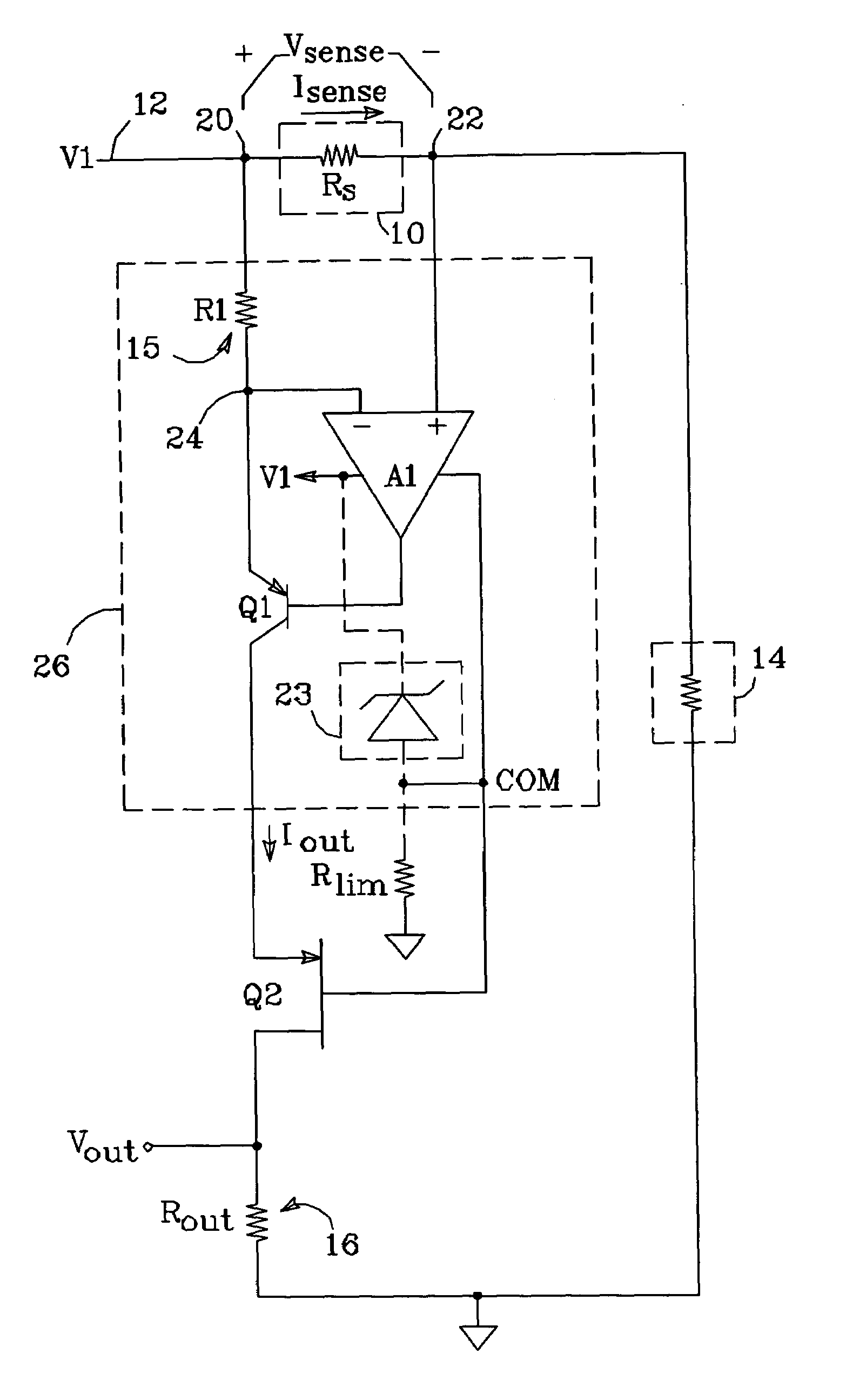
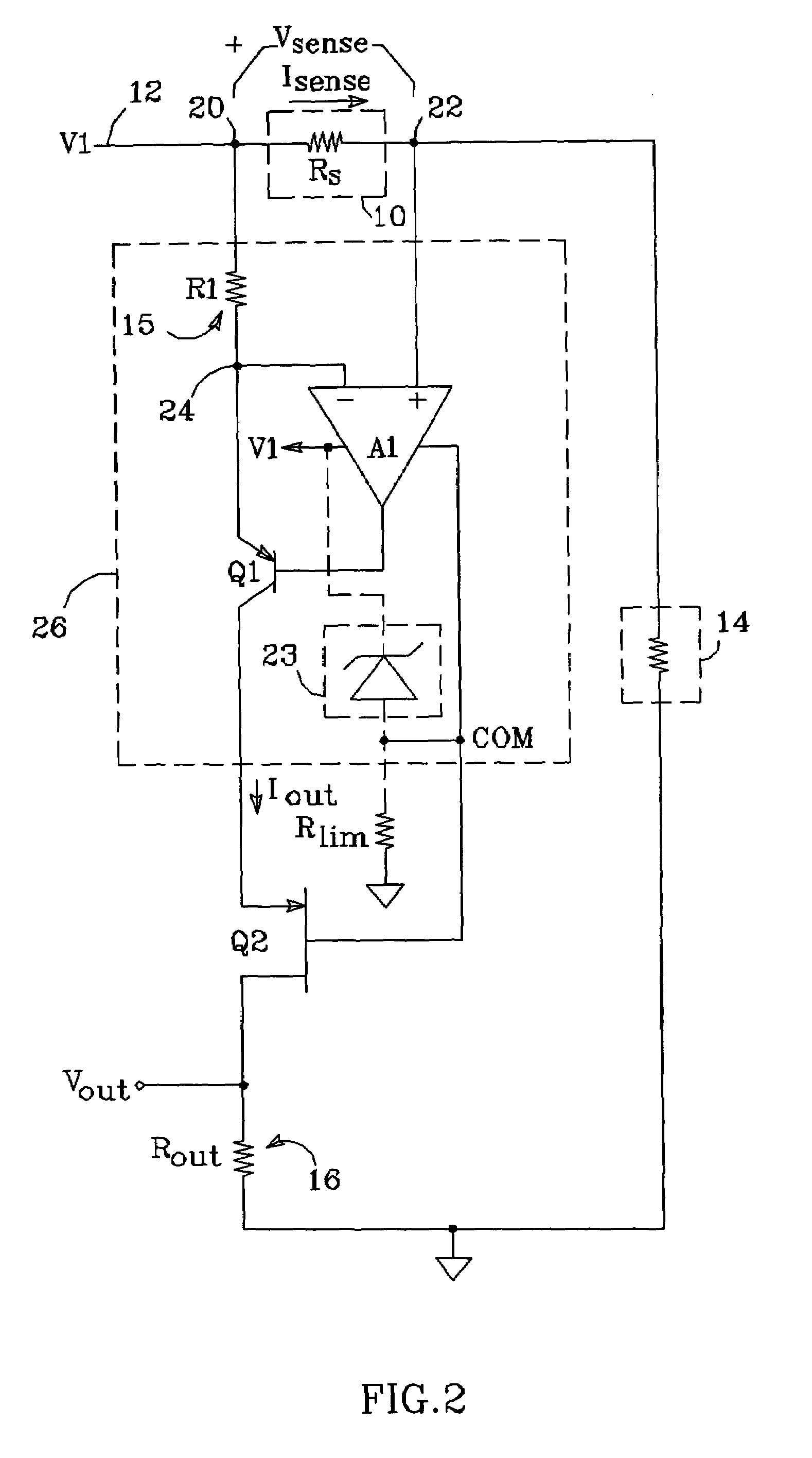
[0020]One embodiment of a high side current monitor circuit in accordance with the present invention is shown in FIG. 2. As described above in relation to FIG. 1, the circuit comprises a sensing element 10, typically a resistor having a resistance Rs (though other devices having a known impedance could also be used), connected between high side and load side terminals 20 and 22 and in series with a signal 12 having a voltage V1. Rs carries a current Isense to a load 14. Op amp A1 is connected across sensing element 10, with its non-inverting input coupled to load side terminal 22 and its inverting input connected to high side terminal 20 via a resistor 15 having a resistance R1. A1 may be powered between V1 and a local circuit common point (COM). Alternatively, the present monitor circuit can include a voltage limiter 23, which, when coupled to ground via a resistance Rlim, enables A1 to be powered from a voltage much lower than the signal common mode voltage. A feedback transistor ...


PUM


Abstract

A high side current monitor circuit includes an op amp which is coupled across a sensing element which carries a current Isense and develops a shunt voltage Vsense. A feedback transistor driven by the op amp output conducts an output current Iout through a resistor to a current output node necessary to make the op amp inputs equal, such that Iout is proportional to Isense. Iout is conducted through a resistor to generate a ground-referred voltage proportional to Vsense. When the common mode voltage of Vsense is greater than the op amp's breakdown voltage, a discrete transistor is connected between the current output node and ground to stand off the voltage across the amp. The monitor circuit is arranged such that it can be powered with a limited fraction of the common mode voltage when used with a discrete transistor, and is self-biased when used without a discrete transistor.

Description

BACKGROUND OF THE INVENTION[0001]1. Field of the Invention[0002]This invention relates to the field of current monitors, and particularly to “high side” current monitors.[0003]2. Description of the Related Art[0004]A high side current monitor is designed to measure the signal current through a sensing element connected in series with a circuit's high side (as opposed to its return side). A shunt voltage proportional to the signal current is developed across the sensing element—typically a small resistor. The current monitor measures the differential voltage across the sensing element, and produces a ground or common-referred output that varies with the sensed current.[0005]A conventional high side current monitor is shown in FIG. 1. A sensing element 10, here a resistor having a resistance Rs, is connected in series with a signal 12 having a voltage V1 and carries a current of interest Isense to a load 14; Rs is typically on the order of 0.1 Ω. An operational amplifier A1 is connect...

Claims


Application Information

Patent Timeline
Patent Type & Authority Patents(United States)
IPC IPC(8): G01R19/00G01R1/20
CPCG01R19/0023G01R1/203G01R19/0092
Inventor BROKAW, A. PAUL
Owner ANALOG DEVICES INC
Why Eureka
Try Eureka