Spade bits with angled sides

a technology of angled sides and spade drill bits, which is applied in the direction of twist drills, manufacturing tools, wood boring tools, etc., can solve the problems of excessive vibration of the spade drill bit and the risk of damaging the material to be cut, and achieve the effect of improving the chip removal properties

Inactive Publication Date: 2005-10-25
TEAM FAIR HLDG
View PDF22 Cites 35 Cited by
  • Summary
  • Abstract
  • Description
  • Claims
  • Application Information

AI Technical Summary

Benefits of technology

[0004]It is an object of the invention to provide a spade bit which overcomes the mentioned drawbacks, and which has enhanced chip removal properties.

Problems solved by technology

Spade bits described in these documents all share the apparent disadvantage that the material to be cut away to form the hole is cut in a relatively large chip, one on each side of the central point.
This requires a relatively large power input to the spade drill bit, and may also cause excessive vibration of the spade drill bit during boring operations.
Further, there is a risk of damaging the material to be cut when the drill bit exits the material on the side opposite the bore starting side of the material.

Method used


Image

  • Spade bits with angled sides
  • Spade bits with angled sides
  • Spade bits with angled sides

Examples


Embodiment Construction

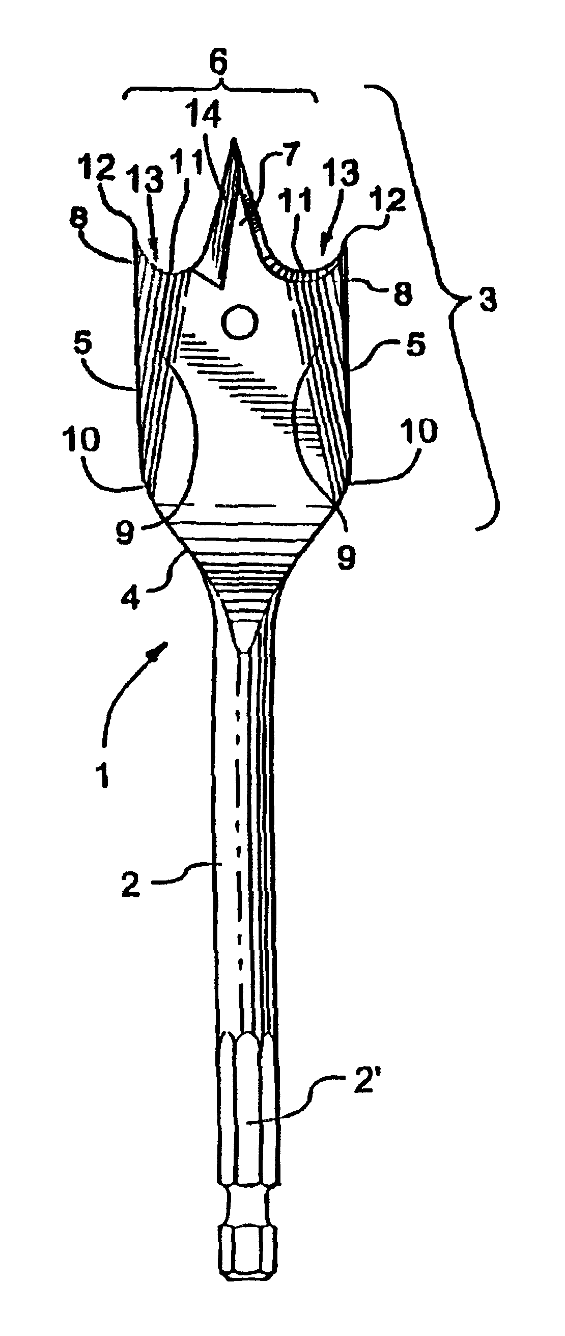
[0069]A first embodiment of a spade drill bit 1 according to the invention is shown in FIGS. 2A to 2J. The spade drill bit 1 has a shaft 2 and a spade head portion 3 arranged on the shaft. The shaft is intended to be fastened in a hand or power tool (not shown), and may have any suitable shape cooperating with the hand or power tool, for instance substantially cylindrical (FIG. 2A) or with a hex end portion 2′ (FIG. 2B). The head portion 3 has a rearward facing bottom edge 4, two longitudinal sides 5 and a forward facing cutting edge 6 having a pointed, generally triangularly shaped tip 7 and outer ends 8. The longitudinal sides of the head portion are bent along a bend 9, in the direction of rotation of the spade drill bit during operation, so that the outer ends of the cutting edge are bent forwards in the rotating direction. The bend 9 runs from a first position 10 at the longitudinal side of the spade head portion to a second position 11 on the cutting edge somewhere between the...


PUM

PropertyMeasurementUnit
perimeteraaaaaaaaaa
shapeaaaaaaaaaa
lengthaaaaaaaaaa

Abstract

A spade drill bit has a shaft and a spade head portion arranged on the shaft. The head portion has a rearward facing bottom edge, two longitudinal sides and a forward facing cutting edge. The cutting edge has a pointed, generally triangularly shaped tip and outer ends. The longitudinal sides of the head portion are bent along a bend in a direction of rotation of the drill bit during operation, so that the outer ends are bent forwards in the rotating direction. The bend runs from a first position at one of the longitudinal sides, closer to the bottom edge than to the cutting edge, and to a second position at the cutting edge between the outer end and the tip.

Description

REFERENCE TO RELATED APPLICATION[0001]This is a formal application based on and claiming the benefit of U.S. provisional patent application No. 60 / 269,346, filed Feb. 20, 2001.FIELD OF THE INVENTION[0002]The present invention generally relates to spade drill bits. In particular, the invention relates to bit configurations adapted to provide enhanced drill hole quality with lowered power requirements and better chip removal.DESCRIPTION OF THE PRIOR ART[0003]Traditional spade drill bits 100 usually have a point 110 and two cutting surfaces 120 generally perpendicular to the material to be cut, see FIGS. 1A to 1D. To enhance the cut surface of the hole, they may also have edge spurs 130 arranged at the outermost tips of the spade, as is shown in FIGS. 1E to 1G. Spade bits of this general design are shown in, for instance, WO 98 / 05459, U.S. Pat. No. 5,221,166, U.S. Pat. No. 5,291,806, U.S. Pat. No. 5,697,738, U.S. Pat. No. 5,700,113 and U.S. Pat. No. 5,061,127. During operation, the poi...

Claims


Application Information

Patent Timeline
Patent Type & Authority Patents(United States)
IPC IPC(8): B23B51/00B27G15/00
CPCB23B51/0009B27G15/00B23B2251/082Y10T408/9093Y10T408/9065Y10T408/901Y10T408/899B23B51/00035
Inventor VASUDEVA, KAILASH C.
Owner TEAM FAIR HLDG
Why Eureka
Try Eureka