a reamer

A reamer and blade technology, applied in the field of reamers, can solve problems such as low machining efficiency, reduced tool life, and impact on workpiece quality, and achieve the effects of improving processing quality, prolonging service life, and ensuring chip removal performance

Inactive Publication Date: 2011-12-07
锑玛(苏州)精密工具股份有限公司
View PDF4 Cites 5 Cited by
  • Summary
  • Abstract
  • Description
  • Claims
  • Application Information

AI Technical Summary

Problems solved by technology

The cooling of the traditional reamer is completely cooled by the cooling hole in the center, which has the following disadvantages: 1. The cooling of the cutting edge is insufficient, resulting in poor surface finish; 2. The chip removal is not ideal, which affects the quality of the workpiece and reduces the tool life. Low machining efficiency

Method used


Image

  • a reamer
  • a reamer
  • a reamer

Examples


Embodiment 1

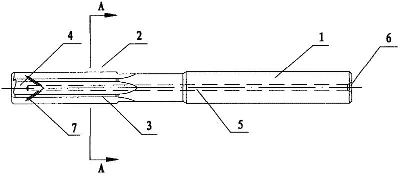
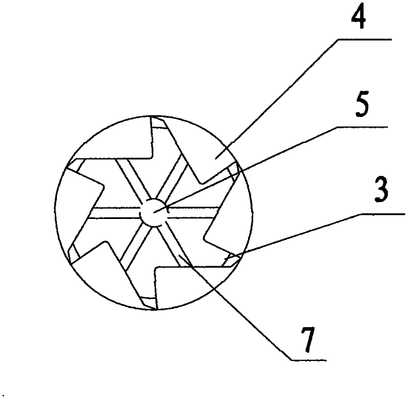
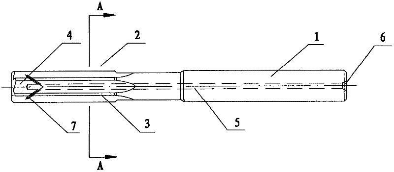
[0015] like figure 1 , 2 As shown, the reamer of this embodiment is processed by using a CNC five-axis linkage grinding machine and independently programming the tool program. The base material is made of hard alloy, and the surface is provided with TIALN-XC coating. Specifically, the reamer includes a shank 1 and a blade 2. The blade 2 is provided with a plurality of side edges 3, and chip removal grooves 4 are arranged between adjacent side edges 3. There is a connected internal cooling hole 5, one end of the internal cooling hole 5 is connected to the water inlet hole 6 provided at the end of the handle 1, and the other end of the internal cooling hole 5 is connected to the drain hole 7 provided in the chip removal groove 4 Connected, the pipeline between the internal cooling hole 5 and the drain hole 7 faces the end of the blade portion 2 .

[0016] During processing, inject cooling water into the reamer through the water inlet hole 6 provided at the end of the shank 1, ...


PUM


Abstract

The object of the present invention is to propose a reamer, which can improve the cooling performance and chip removal performance of the internal cooling reamer, thereby improving the machining quality. The reamer of the present invention includes a shank and a blade. The blade is provided with a plurality of side edges, and chip removal grooves are arranged between adjacent side edges. An internal cooling hole, one end of the internal cooling hole is connected to the water inlet hole provided at the end of the handle, and the other end of the internal cooling hole is connected to the drain hole provided in the chip removal groove. During the processing, the reamer is injected with cooling water through the water inlet hole at the end of the shank, and the cooling water flows through the inner cooling hole to cool the reamer, and finally passes through the hole provided in the chip removal groove. Drain holes are used to discharge the iron chips accumulated in the chip removal groove, which greatly improves the chip removal performance, thereby improving the processing quality, prolonging the service life of the tool, and reducing the use cost of the tool.

Description

technical field [0001] The invention belongs to the technical field of tool manufacturing, and in particular relates to a reamer. Background technique [0002] The reamer is used to ream the hole that has been drilled (or reamed) on the workpiece, mainly to improve the machining accuracy of the hole and reduce the roughness of its surface. It is a tool for finishing and semi-finishing the hole. , the machining allowance is generally small. With the development of the machinery industry, users have put forward higher requirements for product processing quality, processing reliability, processing efficiency, and tool delivery time. The cooling of the traditional reamer is completely cooled by the cooling hole in the center, which has the following disadvantages: 1. The cooling of the cutting edge is insufficient, resulting in poor surface finish; 2. The chip removal is not ideal, which affects the quality of the workpiece and reduces the tool life. The machining efficiency i...

Claims


Application Information

Patent Timeline
Patent Type & Authority Applications(China)
IPC IPC(8): B23D77/00B23Q11/10
Inventor 李振丰孔小波周东阳
Owner 锑玛(苏州)精密工具股份有限公司
Why Eureka
Try Eureka