
Small drill

一种钻头、小型的技术,应用在修钻、麻花钻、钻具附件等方向,能够解决不能形成、无法实现排出切屑、切屑排出性能恶化等问题

Inactive Publication Date: 2004-02-11
MITSUBISHI MATERIALS CORP
View PDF0 Cites 6 Cited by
  • Summary
  • Abstract
  • Description
  • Claims
  • Application Information

AI Technical Summary

Problems solved by technology

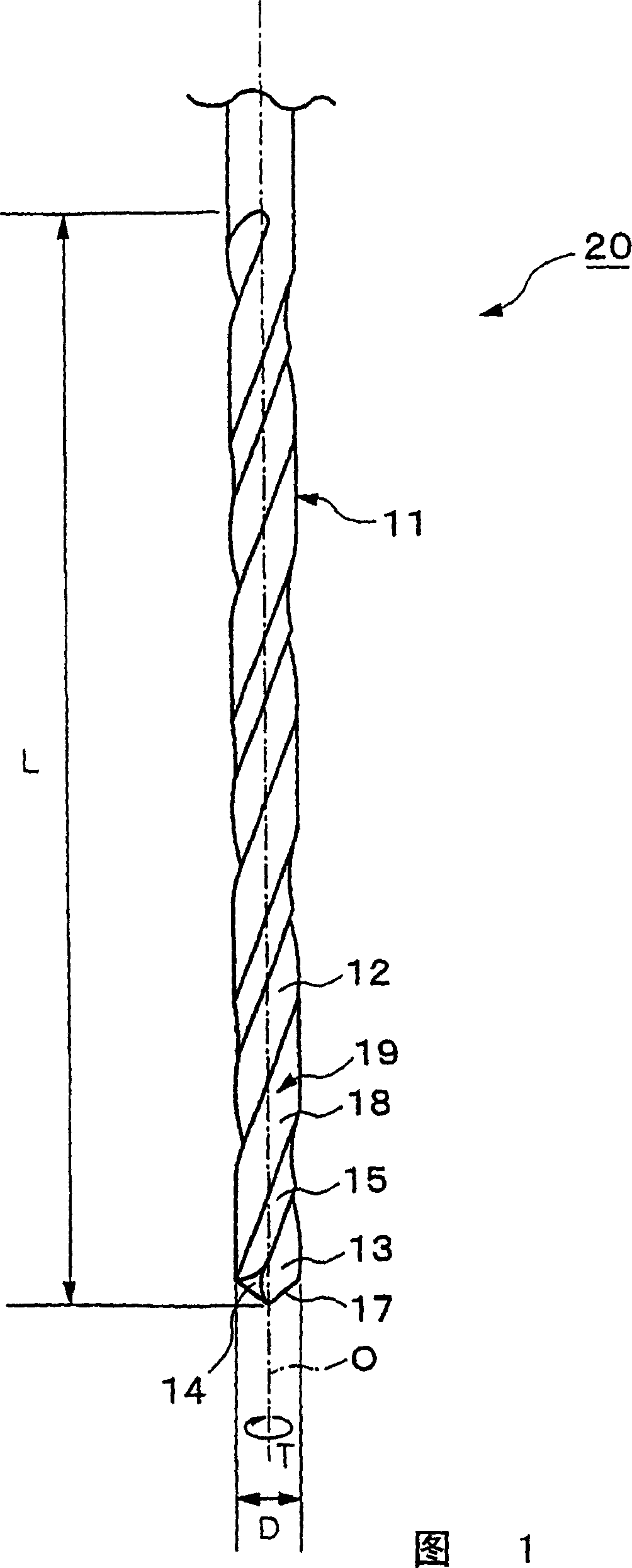
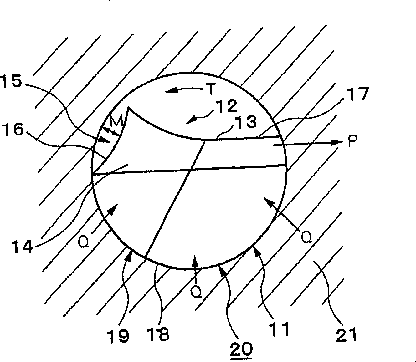
[0006] However, since there is only one chip discharge flute 2 provided on the peripheral surface of the cutting edge to ensure high rigidity, the space for chip discharge is smaller than conventional small drills with two chip discharge flutes. , resulting in poor chip discharge that deteriorates the chip discharge performance and causes chip clogging
[0007] In addition, since the drill bit clearance depth a of the shovel back surface 5 located behind the edge 4 in the direction of rotation is very small, a space of sufficient size to discharge chips cannot be formed, so that the task of chip discharge cannot be achieved.
[0008] As a result, especially in the machining of extremely small diameter deep holes with a hole diameter of 0.5 mm or less and a ratio of hole depth to hole diameter of 10 or more, chip discharge failures frequently occur, so it is not possible to fully adapt to the recent further reduction in hole diameter and further deepening of holes. deep request

Method used


Image

  • Small drill
  • Small drill
  • Small drill

Examples


experiment example

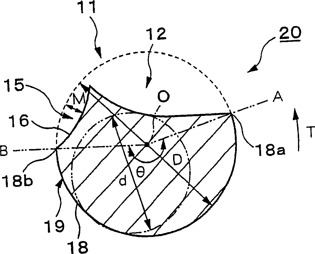
[0070] A small drill that is an example of the present invention is used as Experimental Examples 1 to 5, a small drill with a core thickness ratio d / D smaller than the above-mentioned range of the present invention is used as Comparative Example 1, and a small drill with a complementary angle θ smaller than the above-mentioned range of the present invention is used as a comparative example 2. As a conventional example, a small drill with two chip discharge grooves 12 provided at the tip 11 is used as conventional example 1, and a small drill with one chip discharge flute 12 provided at the tip 11 but without a grooved portion 15 is used. Small drills were used as Conventional Examples 2 to 4, and drilling tests of workpieces were performed using these examples. In addition, in Experimental Examples 1 to 5, Comparative Examples 1 and 2, and Conventional Example 1, the helix angle of the chip discharge flute 12 was 40°, while in Conventional Examples 2 to 4, the helix angle of t...


PUM


Abstract

A small drill includes one chip-discharging flute which is helically formed in the exterior surface of a cutting portion of the small drill. The small drill also includes a flute-shaped portion which is formed in the front region of the chip-discharging flute in the rotating direction, which is connected to the chip-discharging flute, and which is open at the exterior surface of the cutting portion. The core diameter ratio d / D, in percent, of the small drill is set to 60% or more, and a margin angle θ thereof is set to 120 DEG or more.

Description

technical field [0001] The present invention mainly relates to a cutting tool such as a small drill for drilling small-diameter deep holes in printed substrates. [0002] In addition, this application is based on the patent application (patent application 2000-346953) filed in Japan, and takes in the description content of this Japanese application as a part of this specification. Background technique [0003] In general, when the drilled hole diameter of a small drill bit is very small, a small-diameter rod-shaped tool tip with a diameter of about 0.05 to 3.175 mm, for example, should be provided on the top of the drill body, and a small-diameter rod-shaped tip portion with a diameter of about 0.05 to 3.175 mm should be provided at the rear end for clamping the drill body. A drill rod with a larger diameter on the rotating shaft of the working mechanism, which is integrally connected with the tip of the tool by welding or interference fit. The material of the tool tip is u...

Claims


Application Information

Patent Timeline
Patent Type & Authority Applications(China)
IPC IPC(8): B23B51/00B23B51/02
CPCY10S408/705B23B2251/241B23B2251/201B23B2251/406B23B51/02Y10T408/9097Y10T408/89B23B51/00
Inventor 金子和弘小谷二郎
Owner MITSUBISHI MATERIALS CORP
Learn More