Slew rate controlling method and system for output data
a technology of output data and control method, applied in the direction of logic circuit coupling/interface arrangement, pulse technique, instruments, etc., can solve the problem of worsening the data window of an output due to no control rate, and achieve stable high-speed data transfer and improved output window
- Summary
- Abstract
- Description
- Claims
- Application Information
AI Technical Summary
Benefits of technology
Problems solved by technology
Method used
Image
Examples
first embodiment
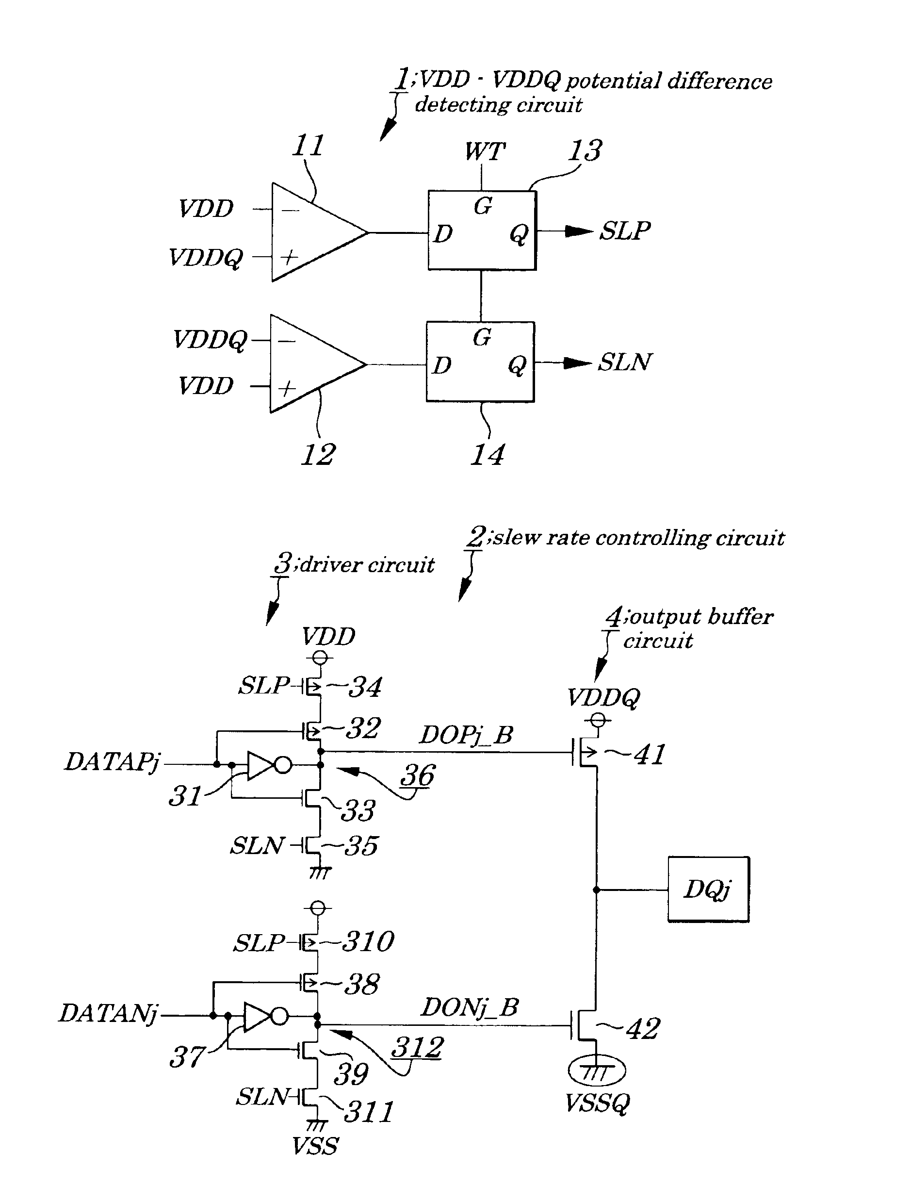
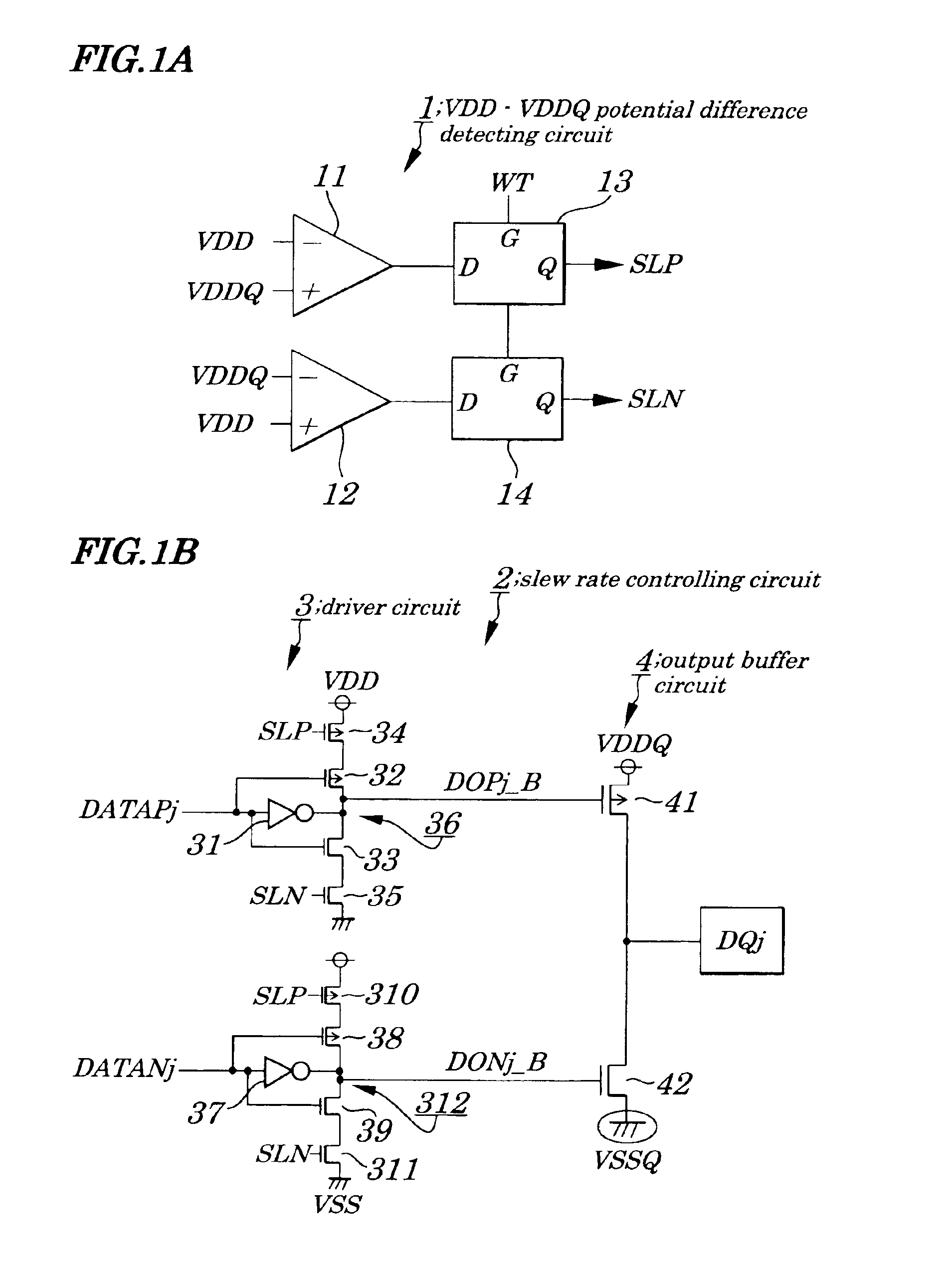
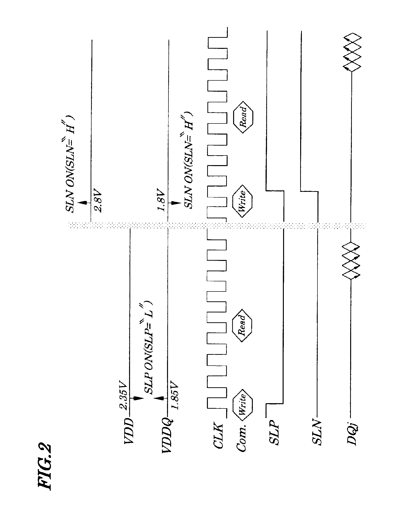
[0031]FIGS. 1A and 1B are block diagrams showing basic configurations of circuits to perform a slew rate controlling method for output data according to a first embodiment of the present invention. FIG. 2 is a diagram explaining operations to be performed by the slew rate controlling method for output data according to the first embodiment. FIG. 3 is a diagram showing concrete configurations of a VDD−VDDQ potential difference detecting circuit according to the first embodiment. FIG. 4 is a diagram showing concrete configurations of a slew rate controlling circuit and an output buffer circuit to be used when the slew rate controlling method of the first embodiment is applied to achieve control on output data of a DDR (Double Data Rate) SDRAM. FIG. 5 is a diagram explaining operations to be performed by the slew rate controlling method for output data using circuit configurations shown in FIG. 4. FIG. 6 is a diagram showing improvements of a tDQSQ value (Alternate-Current characterist...
second embodiment
[0066]Basic configurations employed in a second embodiment are the same as those in the first embodiment. However, a slew rate controlling method differs from that in the first embodiment in that timing with which results from comparison of a potential difference between power supplies VDD and VDDQ in a VDD−VDDQ potential difference detecting circuit are sampled is different.
[0067]That is, in the first embodiment, the results from comparison of a potential difference between the power supplies VDD and VDDQ are sampled when a WRITE command is received. However, timing of the sampling is not limited to this case. In the second embodiment, results from comparison of a potential difference are sampled when any one of an MRS (Mode Register Set) command being a set command for a register to set an operating mode of an SDRAM, an EMRS (Extended Mode Register Set) command being a set command for an extended register to set an operating mode of the SDRAM, an ACTIVE command being a command to ...
PUM
 Abstract
Description
Claims
Application Information
 - R&D
- Intellectual Property
- Life Sciences
- Materials
- Tech Scout
- Unparalleled Data Quality
- Higher Quality Content
- 60% Fewer Hallucinations
Browse by: Latest US Patents, China's latest patents, Technical Efficacy Thesaurus, Application Domain, Technology Topic, Popular Technical Reports.
© 2025 PatSnap. All rights reserved.Legal|Privacy policy|Modern Slavery Act Transparency Statement|Sitemap|About US| Contact US: help@patsnap.com


