Vehicle passenger authorization system

a technology for passenger authorization and vehicle, applied in the field of security systems, can solve the problems of high delay, inability to improve traffic flow through security checkpoints, and inability to use biometric technology stationaryly, and achieve the effect of low data rate and low cos

Inactive Publication Date: 2005-10-25
S T S
View PDF10 Cites 102 Cited by
  • Summary
  • Abstract
  • Description
  • Claims
  • Application Information

AI Technical Summary

Benefits of technology

[0007]The present invention solves the problems encountered at conventional security gates by providing an automated system that authorizes entry into a secured area based on vehicle and passenger identification that occur while the vehicle is approaching the gate. As a result, the vehicle need not stop in order to verify the identification of the vehicle and its occupants.
[0009]The invention contains multiple physical zones through which a vehicle must pass. The zones are used to alert the passengers to the security requirements and manage the authorization process using procedures that control the flow of traffic while avoiding vehicle accidents when security violations occur. The invention uses a voice recognition system to achieve biometrics identification of personnel in a moving vehicle. The invention also includes enhanced fingerprint biometrics measuring for identification of personnel in a moving vehicle.
[0011]In the present invention, fingerprints are read by a device within the vehicle. The transmission of the fingerprint data is accomplished using a number of standard radio and / or optical communications technologies. The vehicle equipment is designed for transmission only, using visual signage to communicate with the driver for the return link to the vehicle. This reduces the cost oaf the in-vehicle equipment.
[0012]The data rate required to upload the biometrics data is low. This allows implementation of low cost solutions. The biometrics device in the vehicle preferably is energized using RF energy from a stationary transmitter. The biometrics device in the vehicle has an antenna designed to receive RF energy from the transmitter, convert it into electrical power, which is then used to operate the electronics of the device, including the biometric measuring device. The user is presented with an audible or visual indicator when the device has converted enough of the RF energy into power stored in the device fro it to operate. The user then places a thumb on the biometrics fingerprint reader pad on the device. The device automatically reads the fingerprint and transmits the biometric data. Low power logic devices operating on a few nanowatts are available from chip manufacturers for constructing such a device. Using external RF to power the device eliminates the requirement for an internal battery. The biometric data is transmitted from the vehicle to a receiver located nearby. Data is transmitted in packets that contain the identity of the person entering data, and where implemented vehicle data. The transmitted data is passed to the VPAS computer for analysis.
[0013]VPAS is designed to authenticate a driver and his vehicle. VPAS can also assists in preventing unauthorized personnel or vehicles from entering. In order to authenticate all the occupants of a vehicle, VPAS must be able to determine the number within the vehicle. When biometric data is being entered, VPAS counts the number of unique entries that take place. This value is subsequently used to determine admissibility of the vehicle when it passes through later zones in the multi-zone staging area.

Problems solved by technology

However, if security regulations require use of rigorous authorization procedures, and if the number of people entering is large and personally unfamiliar to the guards, the time necessary to complete authorizations may result in excessive delays.
Furthermore, authorization based on human observations is prone to human error.
Unfortunately, many of these implementations require the person being screened to physically approach sensing devices and submit themselves physically for examination.
In this respect, the stationary use of biometrics technology will not improve traffic flow through a security checkpoint.

Method used


Image

  • Vehicle passenger authorization system
  • Vehicle passenger authorization system
  • Vehicle passenger authorization system

Examples


Embodiment Construction

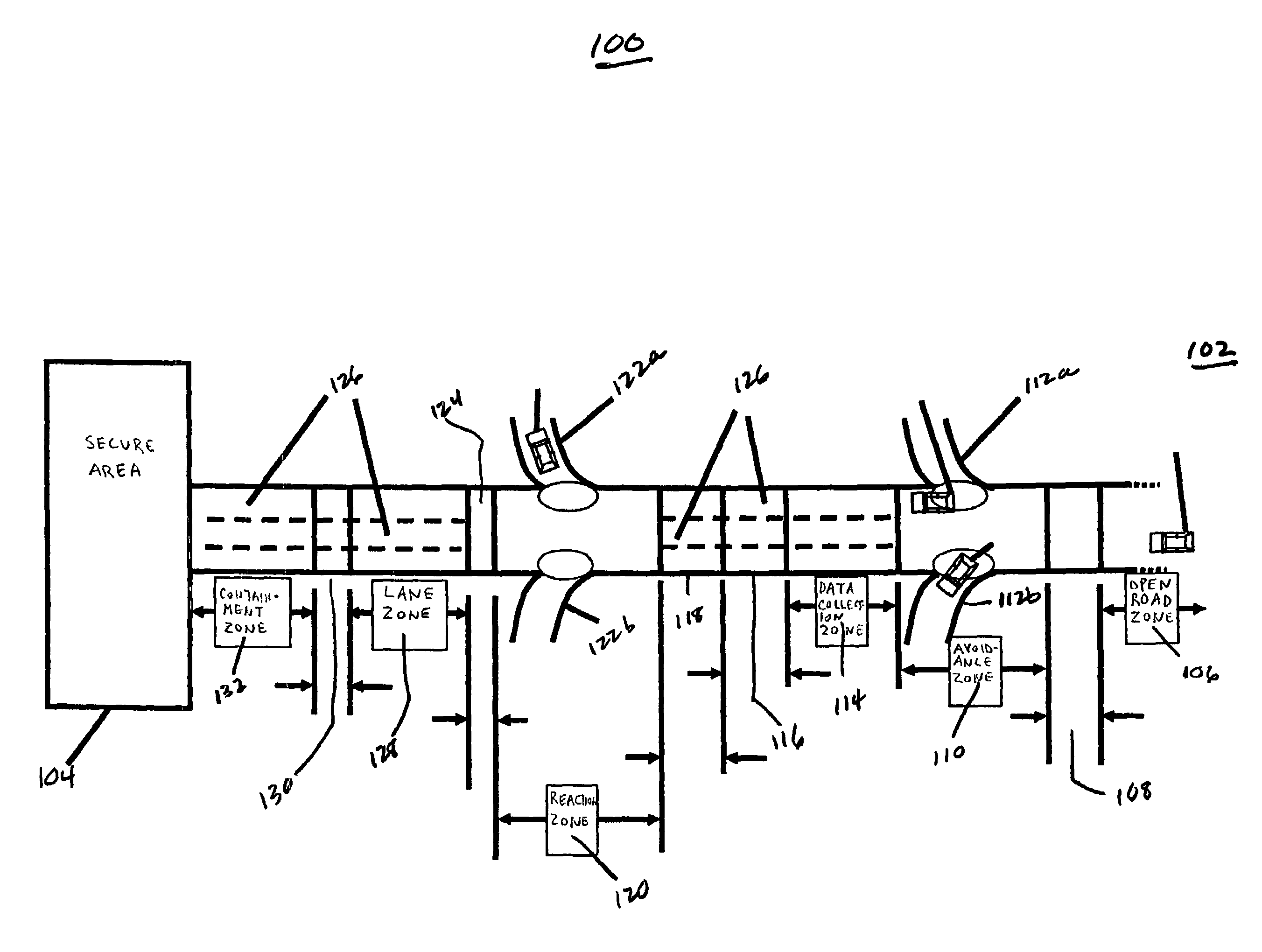
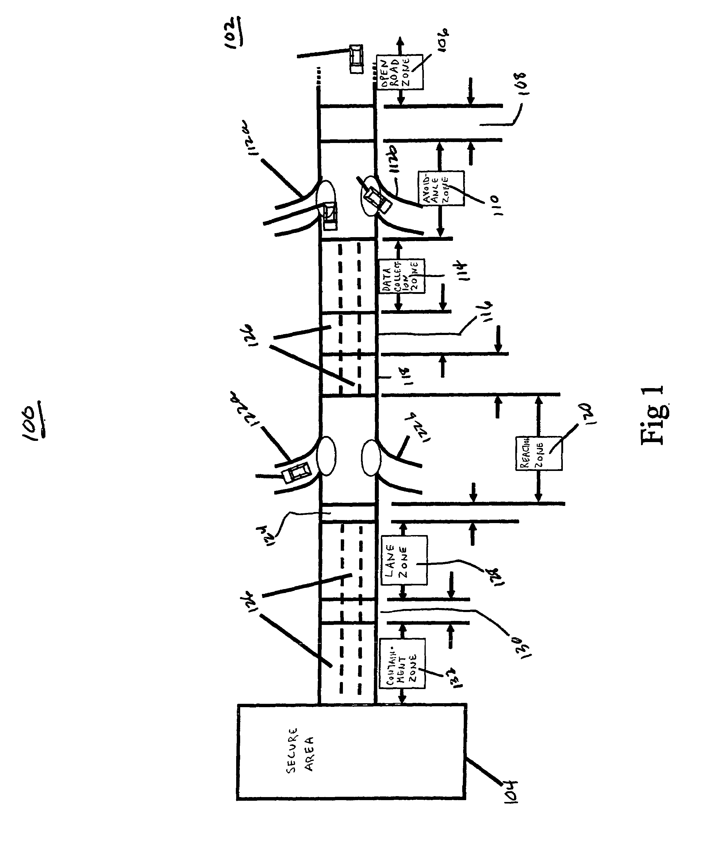
[0019]FIG. 1 shows one of many alternative embodiments of a vehicle passenger authorization system (VPAS) 100 of the present invention. The VPAS 100 includes a multi-zone staging area 102 (staging area) for regulating traffic flow. In a preferred embodiment, a vehicle must pass through each zone of staging area 102 in order to gain access to secure area 104. The staging area 102 optionally but preferably includes the following zones:

[0020]Open Road Zone 106 is a public road preferably having multiple traffic lanes.

[0021]Alert Zone 108 is sign posted to advise vehicle drivers that the vehicle is about to enter a restricted area. Vehicles can be counted electromechanically in this zone as a means of determining how many vehicles inadvertently enter the zone.

[0022]Avoidance Zone 110 allows drivers to exit the VPAS 100 via exits 112a or 112b. The avoidance zone 110 is sign posted with exit signs for directing vehicles back to public roads or to a non-secured area such as a visitor cente...


PUM


Abstract

A system for authorizing vehicle and passenger entry into a secure area while the vehicle is moving is disclosed. The vehicle passenger authorization system verifies the identity of the vehicle and its occupants while the vehicle is moving, thereby eliminating the need for the vehicle to stop as it approaches a secure area. Vehicle imaging technology is used to identify the vehicle. Biometric technology is used to confirm the identity of the occupants of the vehicle. By combining the biometric information of the occupants with the vehicle identification, an efficient and safe means for automatically controlling the flow of traffic into secured areas is disclosed.

Description

CROSS-REFERENCE TO RELATED APPLICATIONS[0001]This application claims priority to U.S. provisional patent application Nos. 60 / 354,219 filed Feb. 6, 2002; 60 / 375,396 filed Apr. 26, 2002; 60 / 382,339 filed May 23, 2002; and 60 / 389,952 filed Jun. 20, 2002.BACKGROUND OF THE INVENTION[0002]1. Field of Invention[0003]This invention relates to security systems, and, more particularly, to a system for identifying and authenticating a vehicle and its passengers before allowing entry into a secure area.[0004]2. Related Art[0005]Entry points to secure facilities, such as military bases, commonly use require manned gateways to check person identification and prevent access by unauthorized personnel. Historically, this has involved guards who personally verify people's identity. This manual practice has many suitable applications, particularly where the level of security is not high and only a limited set of people are authorized to enter. However, if security regulations require use of rigorous a...

Claims


Application Information

Patent Timeline
Patent Type & Authority Patents(United States)
IPC IPC(8): B60R25/00G05B19/00G08B29/00G06F7/00H04B1/00G07B15/00G07C9/00
CPCG07B15/063G07C9/00087G07C9/257H04L2209/84
Inventor MORGAN, DOUGLAS E.MORGAN, TED G.CHILD, JOSEPH R.
Owner S T S
Why Eureka
Try Eureka