Method of manufacturing a droplet deposition apparatus

a droplet deposition and manufacturing method technology, applied in the direction of resistive material coating, piezoelectric/electrostrictive transducer, transducer type, etc., can solve the problem of difficulty in establishing connections to channel electrodes, and achieve the effect of effective and reliable electrical connection

Inactive Publication Date: 2005-11-01
XAAR TECH LTD
View PDF28 Cites 18 Cited by
  • Summary
  • Abstract
  • Description
  • Claims
  • Application Information

AI Technical Summary

Benefits of technology

[0009]The attachment of the body to a surface of the base and subsequent deposition of a continuous layer of conductive material over said at least one channel surface and the base surface results in an effective and reliable electrical...

Problems solved by technology

A problem remains of reliably and efficiently establishing electrical connection between the ink channel electrodes and t...

Method used


Image

  • Method of manufacturing a droplet deposition apparatus
  • Method of manufacturing a droplet deposition apparatus
  • Method of manufacturing a droplet deposition apparatus

Examples


Embodiment Construction

[0024]It will be helpful to describe first in some detail, examples of the prior art constructions referred to briefly above.

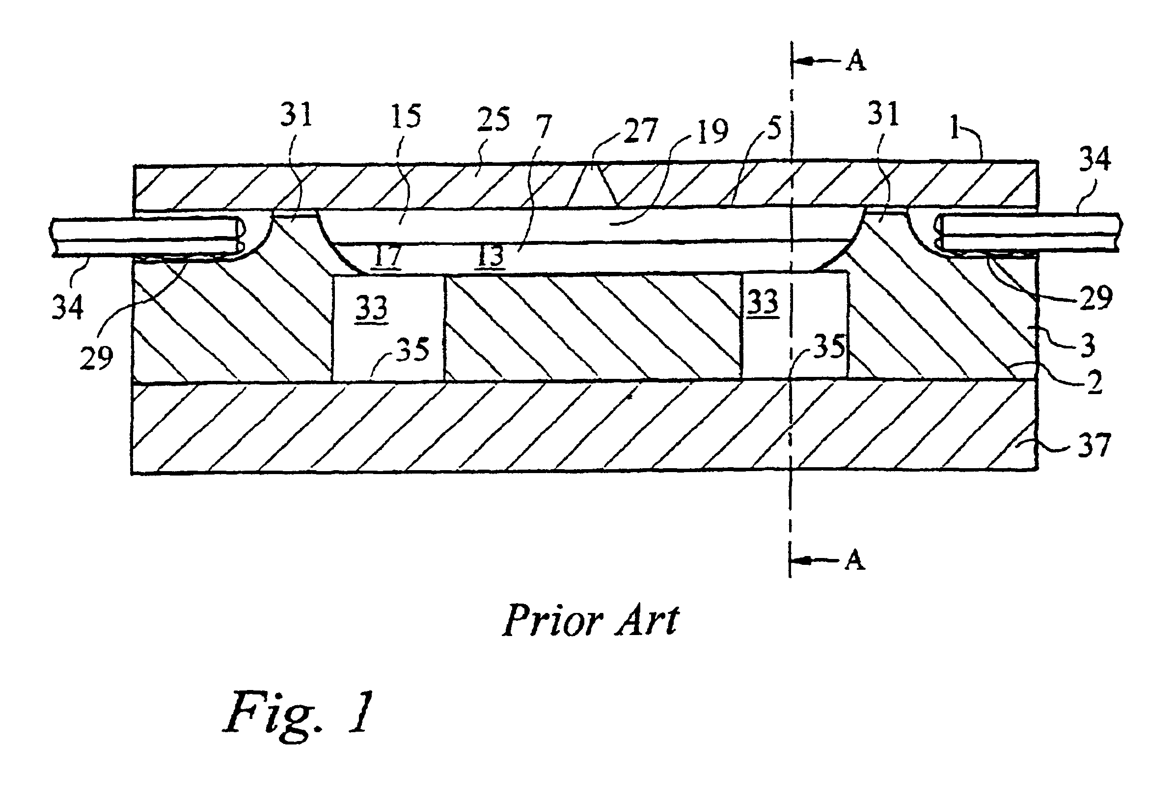
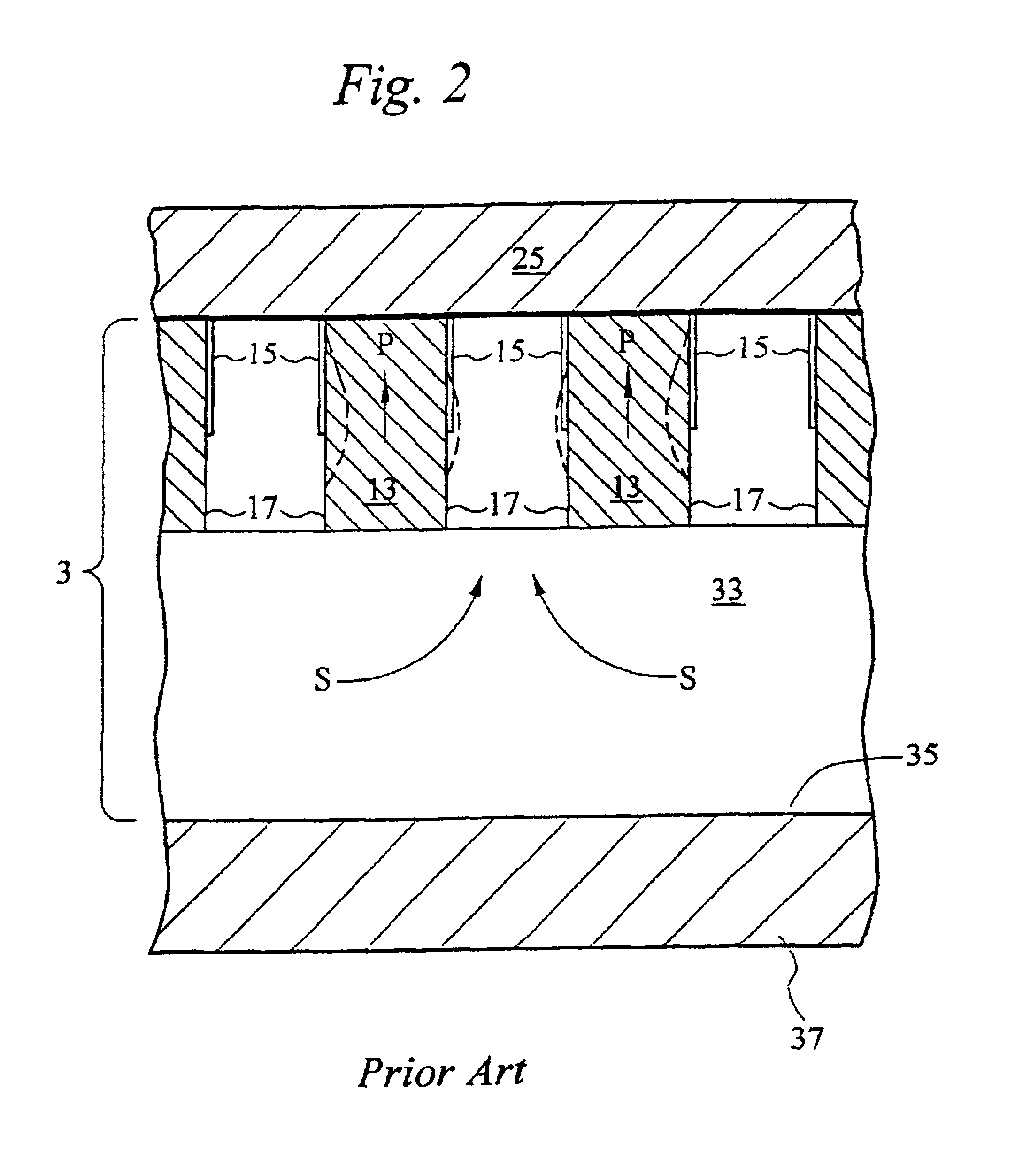
[0025]Thus, FIG. 1 shows a prior art inkjet printhead 1 of the kind disclosed in WO 91 / 17051 and comprising a sheet 3 of piezoelectric material, for example lead zirconium titanate (PZT), formed in a top surface thereof with an array of open-topped ink channels 7. As evident from FIG. 2, which is a sectional view taken along line AA of FIG. 1, successive channels in the array are separated by side walls 13 which comprise piezoelectric material poled in the thickness direction of the sheet 3 (as indicated by arrow P). On opposite channel-facing surfaces 17 are arranged electrodes 15 to which voltages can be applied via connections 34. As is known, e.g. from EP-A-0 364 136, application of an electric field between the electrodes on either side of a wall results in shear mode deflection of the wall into one of the flanking channels—this is shown exaggerated by da...


PUM

PropertyMeasurementUnit
Angleaaaaaaaaaa
Electrical conductoraaaaaaaaaa
Piezoelectricityaaaaaaaaaa

Abstract

A method of manufacturing an ink jet print head includes the steps of bonding a body of piezoelectric material to a base plate and cutting channels into the piezoelectric material to form ink chambers which are actuated by applying voltages to electrodes provided on surfaces of the chambers. The base plate carries IC's which contain the drive circuitry for actuating the ink chambers. To ensure reliable electrical connection between the chamber electrodes and the IC's, the electrodes and conducting tracks on the base plate are formed in a single step by depositing a conductive layer over both the PZT body and the base plate. A step of masking or selective removal of material may be performed to achieve the necessary patterning of the electrodes and tracks.

Description

RELATED APPLICATION DATA[0001]This is a continuation of International Application No. PCT / GB99 / 03799 filed Nov. 15, 1999, the entire disclosure of which is incorporated herein by reference.FIELD OF THE INVENTION[0002]The present invention relates to droplet deposition apparatus, particularly inkjet printheads, components thereof and methods for manufacturing such components.BACKGROUND OF THE INVENTION[0003]A particularly useful form of inkjet printer comprises a body of piezoelectric material with ink channels formed, for example, by disc cutting. Electrodes can be plated on the channel-facing surfaces of the piezoelectric material, enabling an electrical field to be applied to the piezoelectric “wall” defined between adjacent channels. With appropriate poling, this wall can be caused to move into or out of the selected ink channel, causing a pressure pulse which ejects an ink droplet through an appropriate channel nozzle. Such a construction is shown, for example, in EP-A-0 364 136...

Claims


Application Information

Patent Timeline
IPC IPC(8): B41J2/14B41J2/16B41J2/045B41J2/055H04M1/72406H04M1/72409H04M1/72445
CPCB41J2/14209B41J2/1623B41J2/1631B41J2/1632B41J2/1634B41J2/1643B41J2/1609Y10T29/49155B41J2002/14491B41J2202/03B41J2202/12Y10S29/016Y10S29/001Y10T29/49401Y10T29/42B41J2/04
Inventor TEMPLE, STEPHENHARVEY, ROBERT A.SHEPHERD, MARK R.DRURY, PAUL R.CONDIE, ANGUSOMER, SALHADIN
Owner XAAR TECH LTD
Why Eureka
Try Eureka