
Couette device and method to study solids deposition from flowing fluids

a fluid deposition and fluid deposition technology, applied in the field of couette devices, can solve the problems of solid precipitation and deposition in pipes, inability to study fluid flow,

Inactive Publication Date: 2005-11-01
SCHLUMBERGER TECH CORP
View PDF16 Cites 28 Cited by
  • Summary
  • Abstract
  • Description
  • Claims
  • Application Information

AI Technical Summary

Problems solved by technology

In fluids which it is desirable to transport by flowing through pipes or tubing, the deposition of solids from the fluid onto the interior walls of the pipes or tubing can impair fluid flow.
However, when a fluid, such as crude oil, is transported via pipe, such as from a geologic formation to a wellhead via production tubing or from a wellhead or a storage vessel to a refinery via a pipeline, changes in the pressure, temperature, composition, or other parameters of the flowing fluid can lead to precipitation and deposition of solids.
Deposition in a pipe is generally undesirable, because deposited solids can at least partially block the pipe and lead to reductions in the flow rate of the fluid in the pipe and require expensive and time-consuming cleaning of the pipe to restore the maximum flow rate of the fluid.
The study of deposition is difficult for, among other reasons, the difference between fully turbulent flow (that is, flow that is both non-laminar and without the presence of vortices) of a sample fluid in a pipe and the sample fluid in a laboratory scale apparatus.
Common laboratory scale apparatus are generally unable to provide conditions for fully turbulent flow as a result of limitations in apparatus geometry and design.
Further, common laboratory scale apparatus generally cannot provide sufficient levels of pressure and shear to readily study the deposition of solids.

Method used


Image

  • Couette device and method to study solids deposition from flowing fluids
  • Couette device and method to study solids deposition from flowing fluids
  • Couette device and method to study solids deposition from flowing fluids

Examples


Embodiment Construction

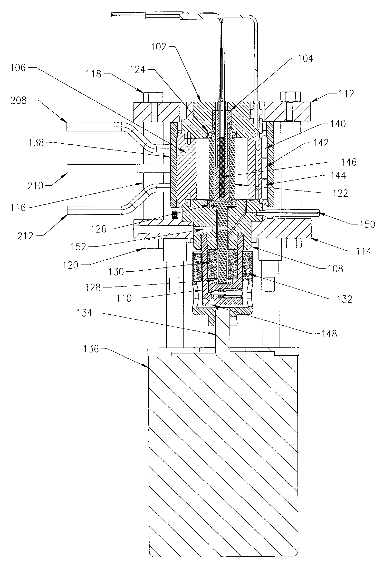
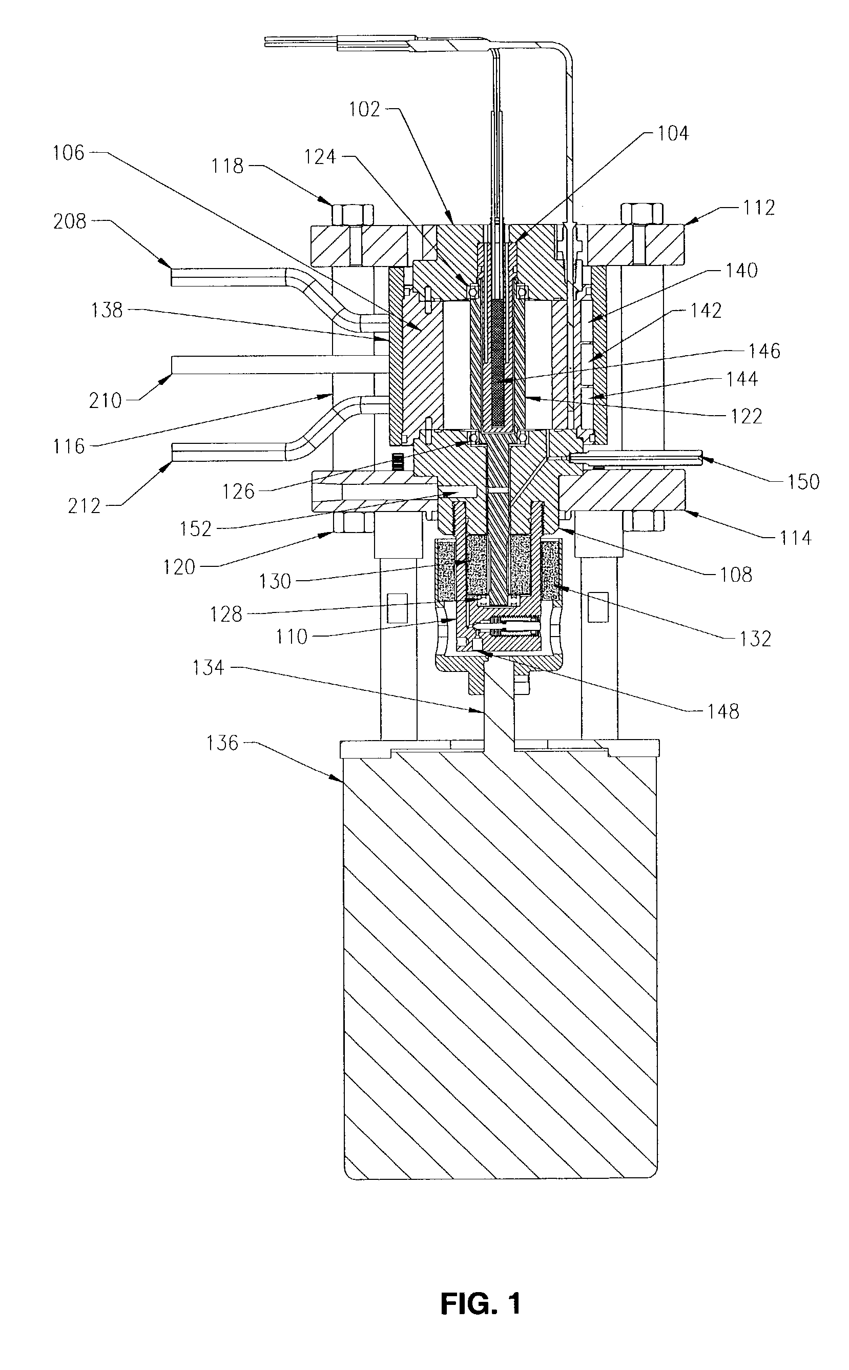
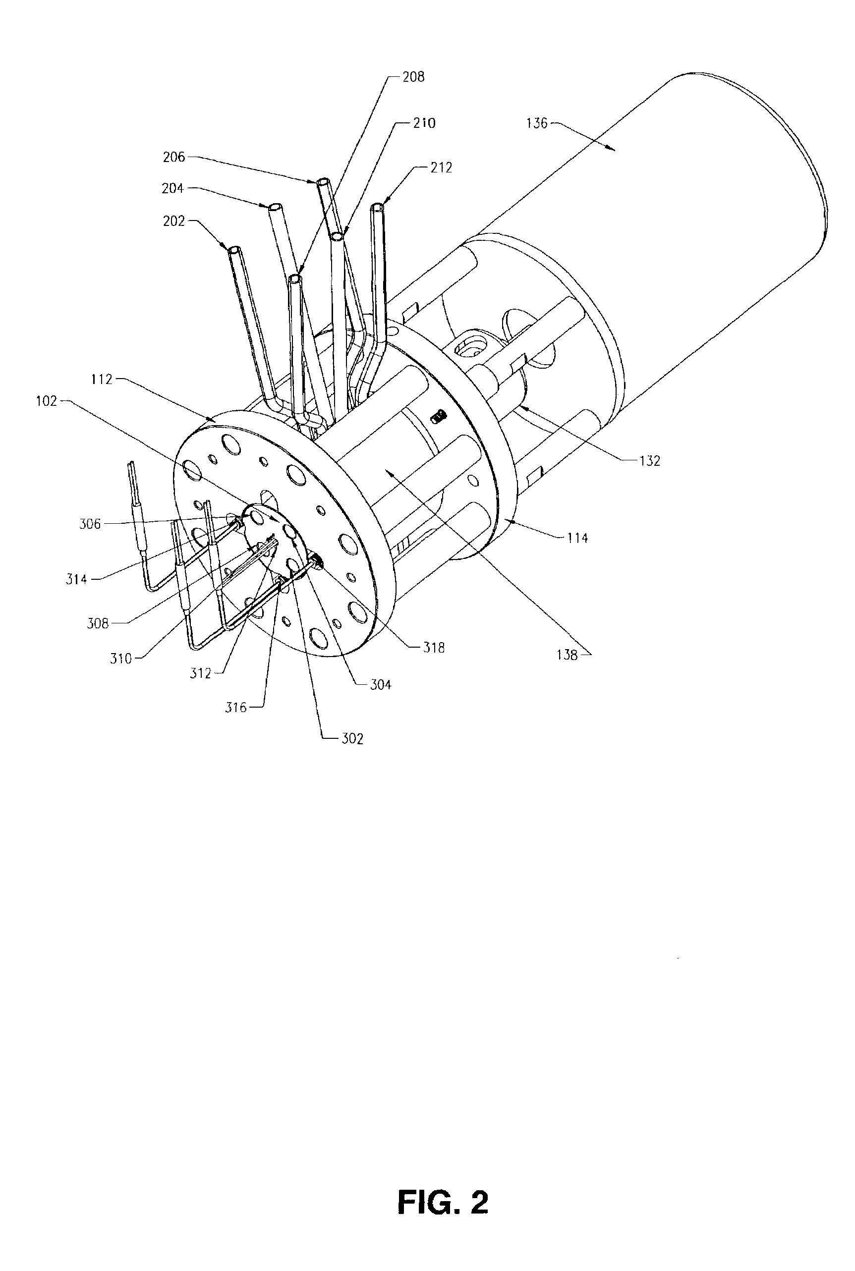
[0022]In one embodiment, the present invention relates to a Couette device, comprising:

[0023]an outer cylinder characterized by having a radius ro;

[0024]an inner cylinder, rotatably connected to and coaxial with the outer cylinder, and characterized by having a radius ri, wherein rio and the outer cylinder and the inner cylinder define an annulus; and,

[0025]a rotatable connector connecting the outer cylinder to the inner cylinder.

[0026]A Couette device is a device in which two or more walls define an annulus and in which an apparatus can impart Couette flow to a fluid (a gas or a liquid) occupying all or part of the annulus. A “cylindrical Couette device,” as the term is used herein, refers to a device comprising an outer, hollow cylinder and an inner cylinder, which define an annulus in the volume between the exterior surface of the inner cylinder and the interior surface of the outer cylinder. These surfaces may be referred to herein as “annular walls.” The term “cylinder” refers ...


PUM

PropertyMeasurementUnit
riaaaaaaaaaa
ro/riaaaaaaaaaa
ro/riaaaaaaaaaa

Abstract

We disclose a method of measuring an emulsion or solids deposition in a fluid sample, comprising charging the sample to a Couette device; subjecting the sample in the Couette device to a pressure, a temperature, and a shear comparable to field conditions; changing at least one of the pressure, temperature, composition, or shear of the sample; and quantifying the type and amount of solids deposited on the interior walls of the Couette device. We also disclose Couette devices which can be used in the method.

Description

BACKGROUND OF THE INVENTION[0001]1. Field of the Invention[0002]The present invention relates generally to the fields of Couette devices and methods involving their use. More particularly, it concerns Couette devices capable of imparting fully turbulent flow to samples, such as crude oil samples, for use in measuring deposition of solids from the samples.[0003]2. Description of Related Art[0004]In fluids which it is desirable to transport by flowing through pipes or tubing, the deposition of solids from the fluid onto the interior walls of the pipes or tubing can impair fluid flow. An example of such a fluid is crude oil. Crude oil from many formations commonly contains solids, often as one or more of waxes, asphaltenes, sulfur, scale, and hydrates.[0005]Paraffin waxes are essentially mixtures of long-chain n-paraffins with carbon chain lengths ranging from C15 to C75+.[0006]Asphaltenes and residual oil components often co-precipitate with the paraffin waxes and result in varying ap...

Claims


Application Information

Patent Timeline
Patent Type & Authority Patents(United States)
IPC IPC(8): G01N33/28G01N15/04G01N33/26G01N11/10G01N11/14G01N33/18G01N33/32G01N33/34
CPCG01N15/04G01N33/2823G01N33/343G01N11/14G01N33/18G01N33/32
Inventor ZOUGARI, MOHAMMED I.HAMMAMI, AHMEDKARAN, KUNALJACOBS, SCOTTRATULOWSKI, JOHN
Owner SCHLUMBERGER TECH CORP
Learn More