Tube-style radiator structure for computer

a radiator structure and computer technology, applied in the direction of laminated elements, semiconductor/solid-state device details, lighting and heating apparatus, etc., can solve the problem of providing a sufficient area for heat dissipation, and achieve the effect of enhancing the efficiency of heat dissipation, facilitating fabrication, and reducing the amount of material used

Inactive Publication Date: 2005-11-01
WANG TUNG YUAN
View PDF10 Cites 15 Cited by
  • Summary
  • Abstract
  • Description
  • Claims
  • Application Information

AI Technical Summary

Benefits of technology

[0005]An object of the present invention is to provide a tube-style radiator structure in which two arc tubes for conducting heat are provided to pass through specifically designed cooling fins, and a base is disposed under the arc tubes with a flat bottom so that the efficiency of heat conduction and the efficiency of heat dissipation can be enhanced substantially.
[0006]Another object of the present invention is to provide a tube-style radiator structure, which can be easily fabricated and can be set up simply.

Problems solved by technology

Hence, how to maximize the contact surface between the cooling fins and the electronic component and how to provide a sufficient area for heat dissipation are problems to be addressed.

Method used


Image

  • Tube-style radiator structure for computer
  • Tube-style radiator structure for computer
  • Tube-style radiator structure for computer

Examples


Embodiment Construction

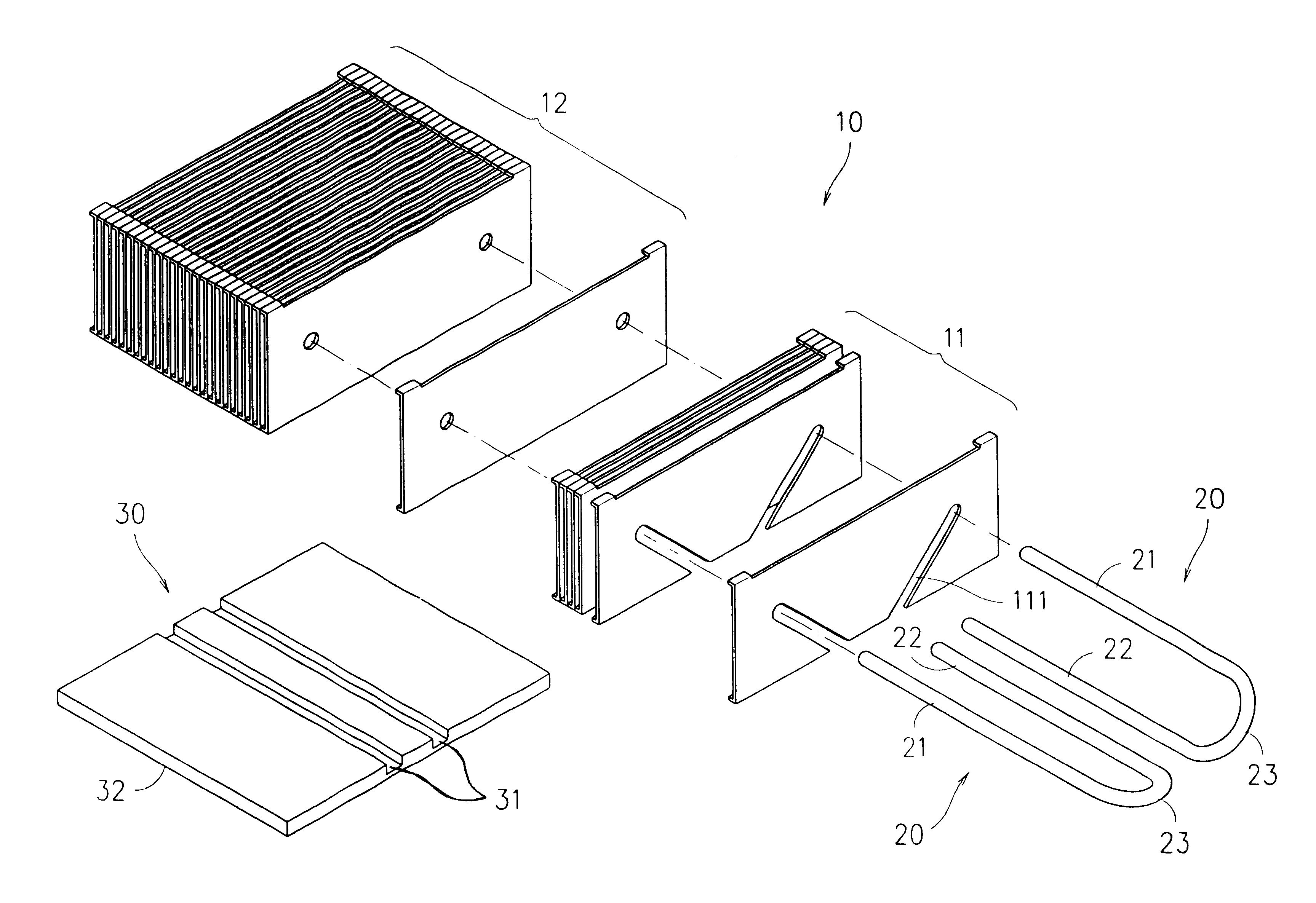
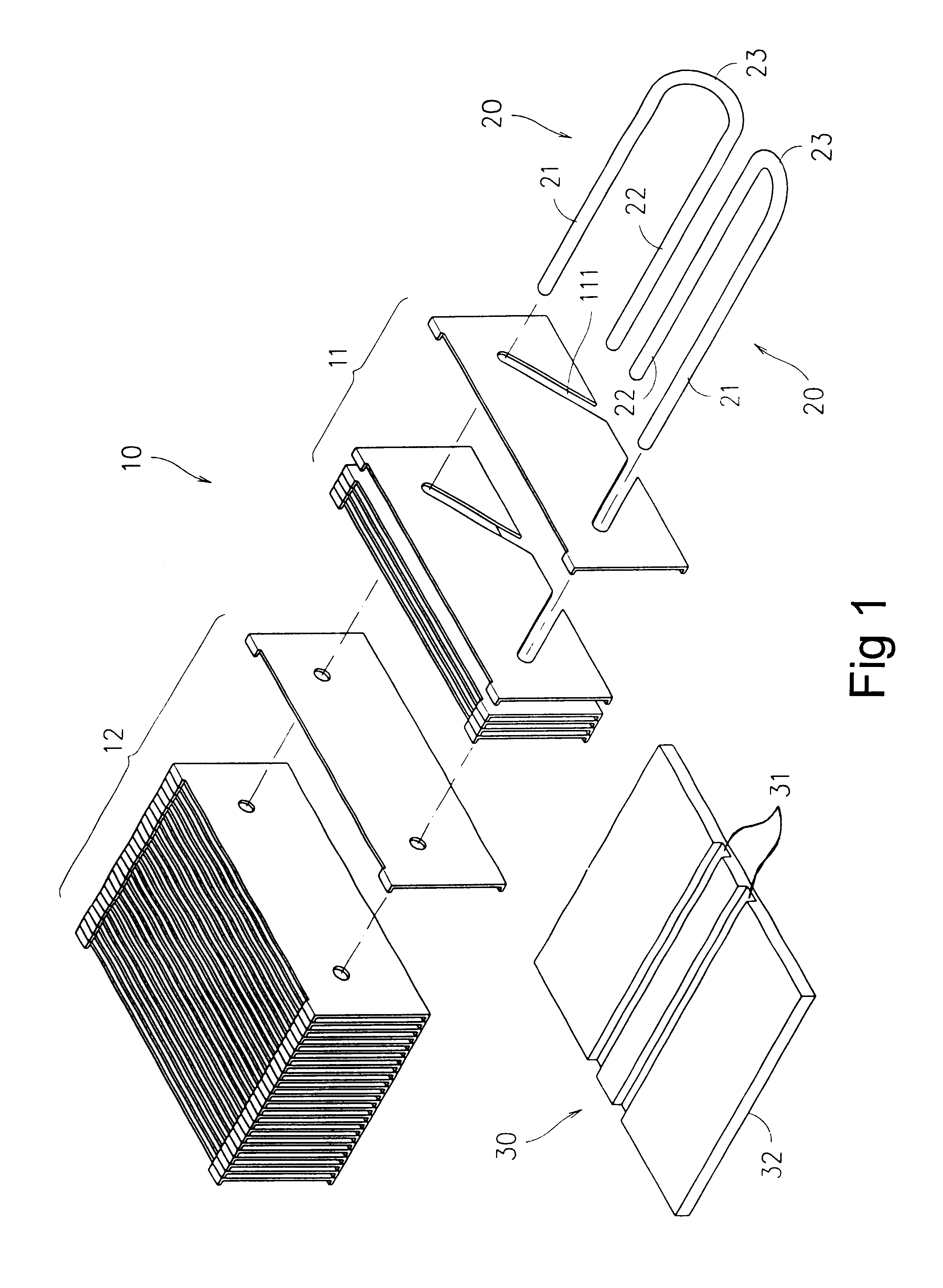
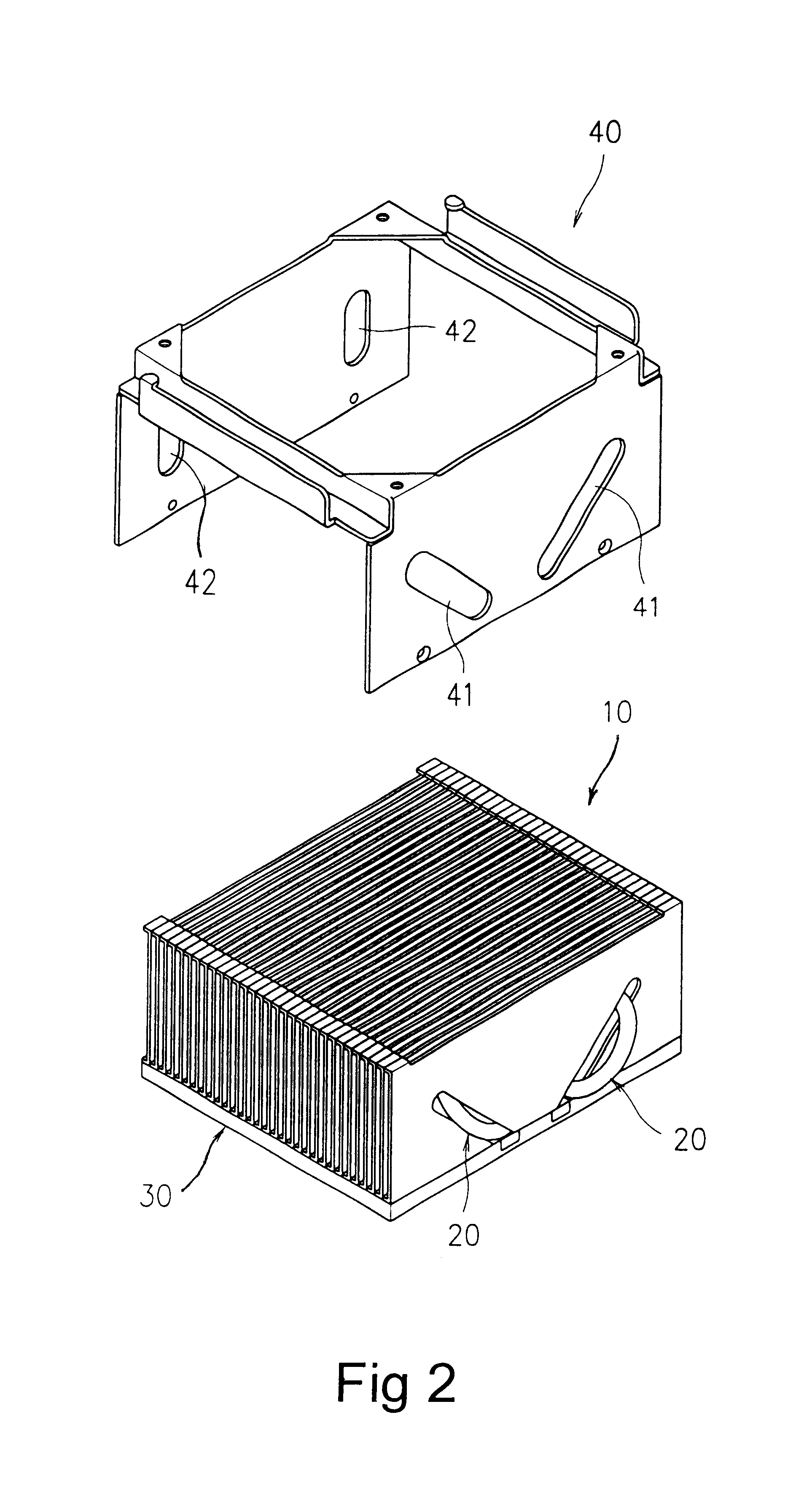
[0012]Referring to FIGS. 1 and 2, a tube-style radiator structure according to the present invention includes an air-cooling fin part 10, two heat conduction tubes 20, a base 30 and a cover 40.

[0013]The air-cooling fin part 10 further includes a plurality of front fins 11 and a plurality of rear fins 12 with each of the front fins 11 having two opposite tapered slots 111 and each of the rear fins 12 having two opposite through holes corresponding to the tapered slots 111 respectively. Also, each of the tapered slots has an open lower end and an angle such as 90° or any other approximate angle is formed between the two tapered slots 111 to constitute a shape of “V”.

[0014]Each of the conduction tubes 20 provides two parallel straight tube sections 21, 22 and an arc tube section 23 to form a shape of “U” so that the conductive tubes 20 is capable of being inserted into the air-cooling fin part 10 by way of the straight tube sections 21 passing through the tapered slots of the front fin...


PUM


Abstract

This invention is a tube-style radiator structure, which includes an air-cooled fins, two heat conduction tubes, a base and a cover. Each of the heat conduction tubes has two straight tube sections and an arc tube section so as to form the shape of “U”. One of the straight tube sections of each heat conduction tube passes through the air-cooling fin part and the other straight tube thereof lies in one of two grooves provided in the base. Accordingly, a large cooling area can be obtained and the efficiency of heat dissipation can be enhanced effectively.

Description

BACKGROUND OF THE INVENTION[0001]1. Field of the Invention[0002]The present invention relates to a tube-style radiator structure for a computer, in particular, to a radiator structure, which provides a high capacity in heat conduction and dissipation.[0003]2. Description of Related Art[0004]Due to the running speed of an electronic component such as the central processing unit (CPU) in a computer increasing rapidly, the demand for higher efficiency of heat dissipation has increased. Currently, air cooling fins and a cooling fan are widely used as the heat dissipation device because direct effect can be achieved and the cost is low. However, it is known that the efficiency of heat dissipation depends on the structure of the cooling fins very much. Hence, how to maximize the contact surface between the cooling fins and the electronic component and how to provide a sufficient area for heat dissipation are problems to be addressed.SUMMARY OF THE INVENTION[0005]An object of the present i...

Claims


Application Information

Patent Timeline
Patent Type & Authority Patents(United States)
IPC IPC(8): F28F3/00F28F3/02H01L23/34H01L23/467H01L23/367H01L23/427F28F1/32
CPCF28F1/32F28F3/02H01L23/3672H01L23/467H01L23/427H01L2924/0002H01L2924/00F28D15/0275
Inventor CHEN, KUO JUI
Owner WANG TUNG YUAN
Why Eureka
Try Eureka