Structure of signal line connector

a signal line connector and connector technology, applied in the direction of coupling devices, two pole connections, two-part coupling devices, etc., can solve the problems of contact error or disconnection of coaxial cables, complicated installation procedures of this design, contact errors, etc., to improve the design of the locating barrel and improve the structure of the signal line connector

Inactive Publication Date: 2005-11-01
CABLENET
View PDF6 Cites 17 Cited by
  • Summary
  • Abstract
  • Description
  • Claims
  • Application Information

AI Technical Summary

Benefits of technology

[0010]The present invention has been accomplished under the circumstances in view. It is therefore the main object of the present invention to provide an improved structure of signal line connector, which eliminates the drawbacks of the aforesaid prior art signal line connector.
[0011]To achieve this and other objects of the present invention, the invention improves the design of the locating barrel, i.e., in addition to the first and second outside annular flanges, the locating barrel further has a pressure collar extended around a periphery and spaced between the first outside annular flange and the second outside annular flange, and an outside annular groove extended around the periphery and defined between the pressure collar and the second outside annular flange. The pressure collar and the second outside annular flange have different outer diameters, so that the locating barrel can be properly deformed to fit different signal lines of different sizes. Further, the outside annular groove buffers and compensates the deformation of the pressure collar and the deformation of the second outside annular flange during installation of the locating barrel in the hollow cylindrical casing.

Problems solved by technology

Therefore, a contact error may occur, or the signal line may be separated from the signal line connector when the signal line stretched.
The installation procedure of this design is complicated.
If the coaxial cable is curved or stretched during installation, the locating member tends to be vibrated and loosened, resulting in a contact error or disconnection of the coaxial cable.
Curving of the protruded part of the locating barrel E destructs the sense of beauty of the signal line connector, and results in a gap between the inside wall of the hollow cylindrical casing D and the outside wall of the locating barrel E.

Method used


Image

  • Structure of signal line connector
  • Structure of signal line connector
  • Structure of signal line connector

Examples


Embodiment Construction

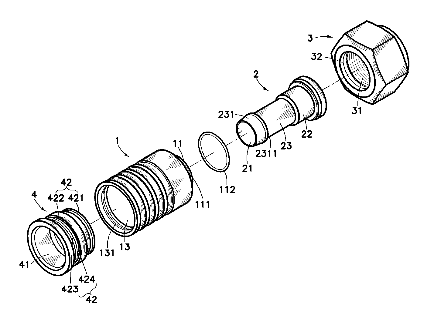
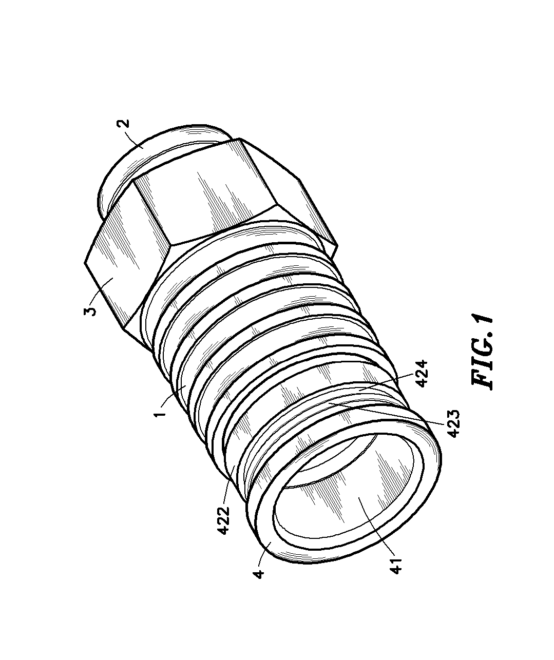
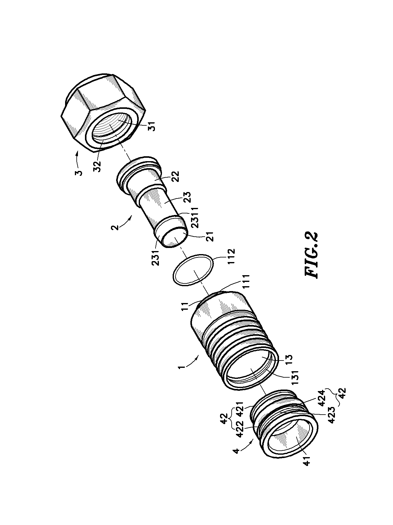
[0021]Referring to FIGS. 1–3, a signal line connector in accordance with the present invention is shown comprised of a hollow cylindrical casing 1, a center holding down tube 2, a locknut 3, and a locating barrel 4.

[0022]The hollow cylindrical casing 1 is mounted on the center holding down tube 2, having a coupling neck 11 at the rear end, an outside annular groove 111 extended around the periphery of the coupling neck 11 to hold a gasket ring 112, a rear coupling hole 12 and a front coupling hole 13 axially aligned in a line and respectively extended through the rear and front ends, and an inside annular groove 131 extended around the inside wall in the front coupling hole 13, and an inside annular flange 1311 extended around the inside wall in the front coupling hole 13 at one side of the inside annular groove 131.

[0023]The center holding down tube 2 has a tube body 23, a barbed portion 231 at the front end of the tube body 23, a receiving portion 22 at the rear end of the tube bo...


PUM


Abstract

A signal line connector includes a locknut, a hollow cylindrical casing, which has a coupling neck extended from one end thereof and fitted into the locknut, a locating barrel fitted into the other end of the casing, the locating barrel having a pressure collar and an outside annular flange extended around the periphery thereof for engaging into the hollow cylindrical casing to force the locating barrel to deform at an amount subject to the size of the signal line used, the pressure collar and the outside annular flange of the locating barrel having different outer diameters, and an outside annular groove defined between the pressure collar and the outside annular flange for buffering and compensating the deformation, and a center holding down tube mounted in the casing and secured to the locknut by the casing for holding down a tubular outer conductor and an outer insulative layer of a signal line against the inside wall of the locating barrel, keeping a center conductor of the signal line axially suspended in the locknut.

Description

[0001]This application claims the priority benefit of Taiwan patent application number 093220049 filed on Dec. 13, 2004.BACKGROUND OF THE INVENTION[0002]1. Field of the Invention[0003]The present invention relates to a signal line connector and, more specifically, to an improved structure of signal line connector, which has the locating barrel so made to fit different signal lines of different sizes and to maintain the sense of beauty of the outer appearance of the signal line connector intact after installation.[0004]2. Description of the Related Art[0005]A conventional signal line connector is known comprising a connector body affixed to a thin tube for accommodating a signal line. After insertion of a signal line into the connector body and the thin tube, a crimping device is used to crimp and distort the thin tube, causing the thin tube to be fixedly secured to the signal line. When crimping the thin tube, the thin tube may break along its seam line. Therefore, a contact error m...

Claims


Application Information

Patent Timeline
Patent Type & Authority Patents(United States)
IPC IPC(8): H01R9/05H01R13/502H01R13/504H01R13/506H01R13/58H01R13/646
CPCH01R9/0524H01R13/502H01R13/5837H01R24/40H01R13/5045H01R13/506H01R2103/00
Inventor CHEN, CHIUNG-LING
Owner CABLENET
Why Eureka
Try Eureka