
Dual stress member conductive cable

a technology of conductive cables and stress members, which is applied in the direction of insulated conductors, power cables, cables, etc., can solve the problems of limited tensile strength and fatigue life of conductive cables, lack of physical strength to carry the tensile load to which the cable is subjected, and add little or no tensile strength, so as to increase the conductivity of the conductive path, and increase the electrical conductivity

Inactive Publication Date: 2005-11-01
SCHLUMBERGER TECH CORP
View PDF13 Cites 23 Cited by
  • Summary
  • Abstract
  • Description
  • Claims
  • Application Information

AI Technical Summary

Benefits of technology

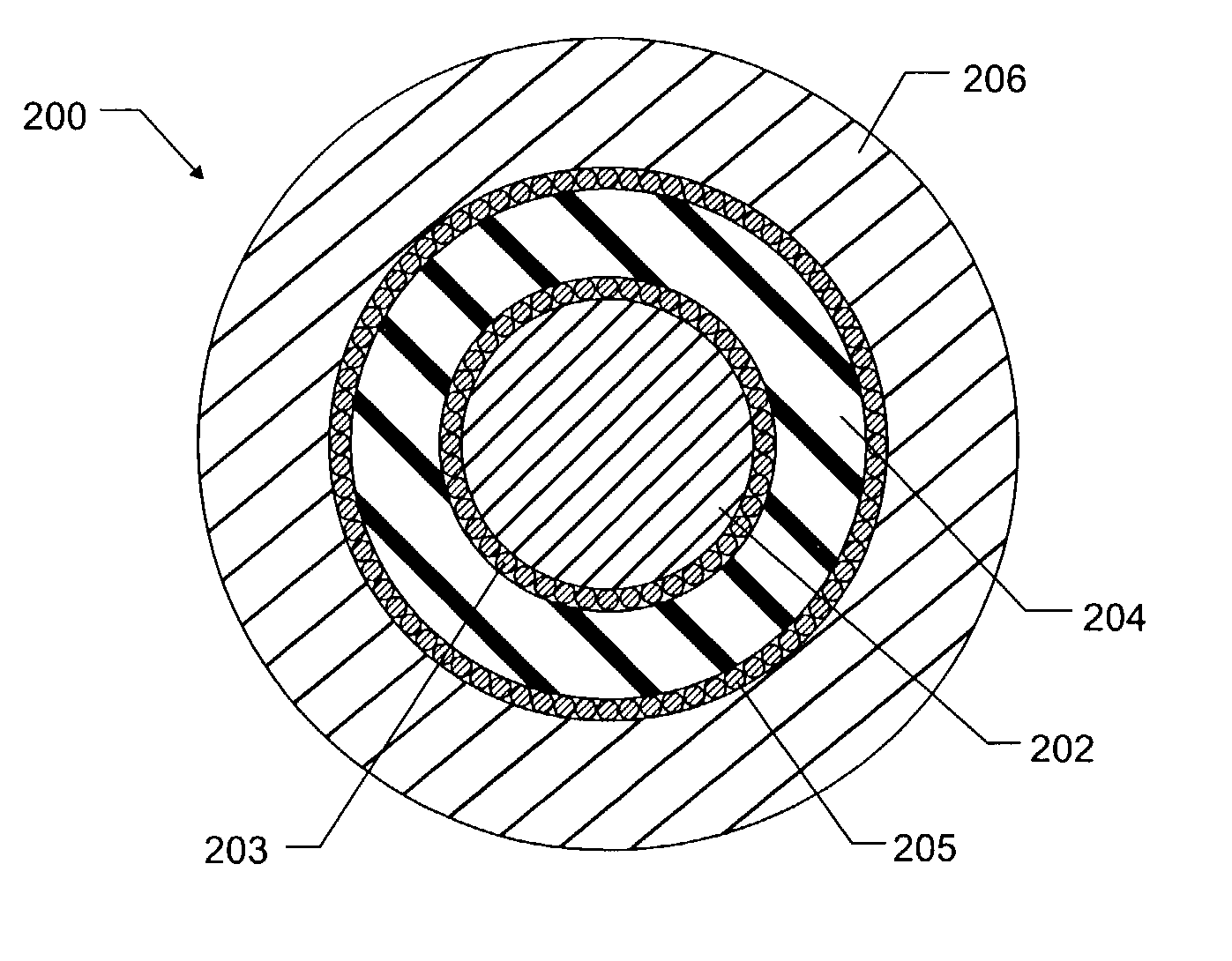
[0010]In another aspect of the present invention, the electrical cable includes a highly conductive coating on the core to increase its electrical conductivity.
[0011]In another aspect of the present invention, the electrical cable includes a highly conductive tape or serve applied to the core to increase its electrical conductivity.
[0012]In yet another aspect of the present invention, the outer surface of the insulating layer is coated in a highly conductive material to increase the conductivity of the conductive path formed by the outer load-bearing member.
[0013]In still another aspect of the present invention, a highly conductive tape or serve is applied to the outer surface of the insulating layer to increase the conductivity of the conductive path formed by the outer load-bearing member.

Problems solved by technology

Such cables typically employ copper wire cores that, although effective electrical conductors, lack sufficient physical strength to carry the tensile load to which the cable is subjected.
However, while this cable has good telemetry capability, its tensile strength and fatigue life are limited to those of the stainless steel tube alone, with the copper core adding little or no tensile strength.

Method used


Image

  • Dual stress member conductive cable
  • Dual stress member conductive cable

Examples


Embodiment Construction

[0018]Illustrative embodiments of the invention are described below. In the interest of clarity, not all features of an actual implementation are described in this specification. It will of course be appreciated that in the development of any such actual embodiment, numerous implementation-specific decisions must be made to achieve the developer's specific goals, such as compliance with system-related and business-related constraints, which will vary from one implementation to another. Moreover, it will be appreciated that such a development effort might be complex and time consuming, but would nevertheless be a routine undertaking for those of ordinary skill in the art having the benefit of this disclosure.

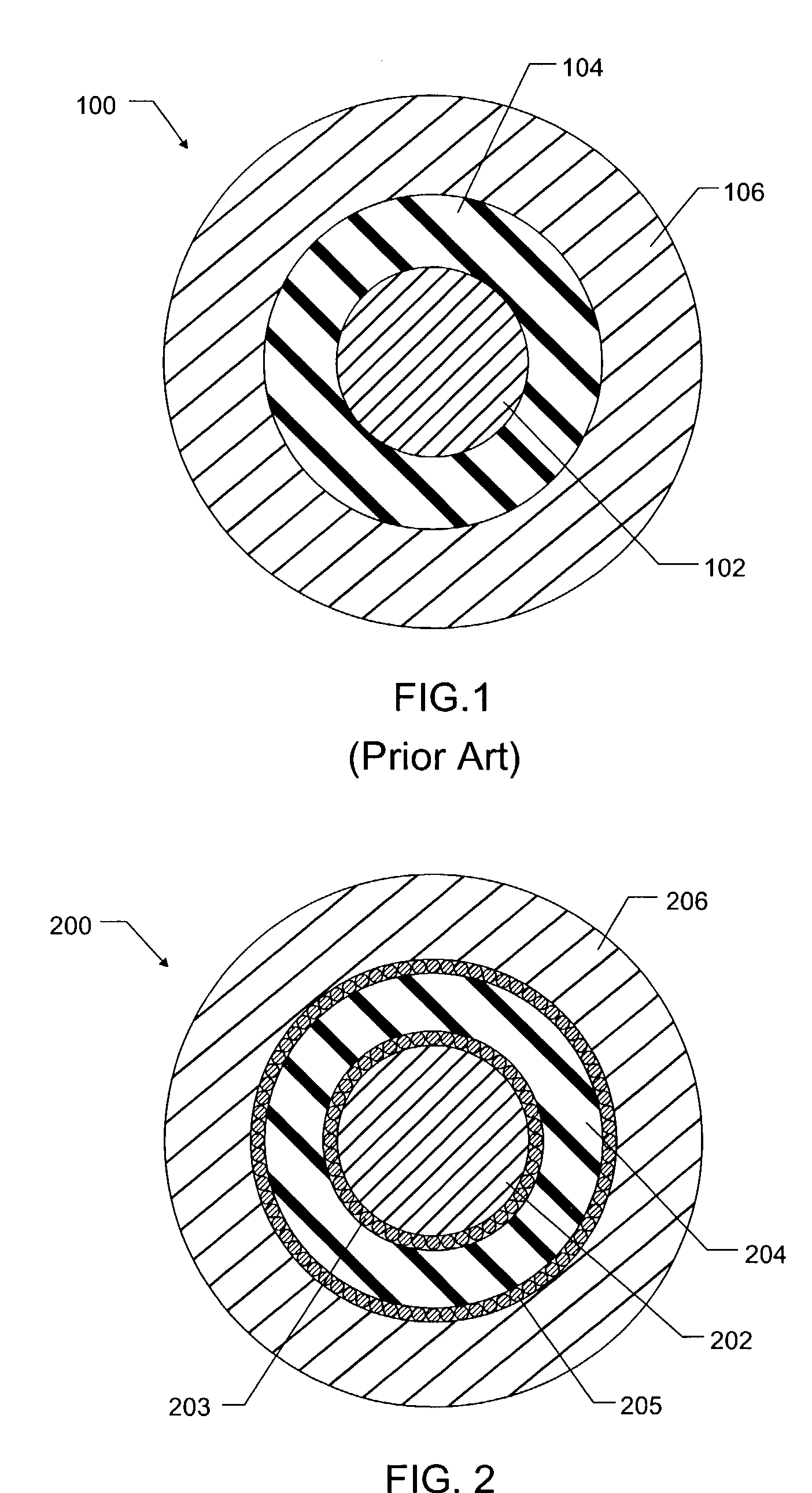
[0019]FIG. 1 depicts, in cross section, a prior art conductive slickline cable designed for oilfield usage. The cable 100 comprises a solid copper core conductor 102, a surrounding electrically insulating layer 104, and a tubular outer cover or member 106 formed of a metal alloy....


PUM

PropertyMeasurementUnit
diameteraaaaaaaaaa
diameteraaaaaaaaaa
thicknessaaaaaaaaaa

Abstract

A dual stress member electrical cable includes an electrically conductive, load-bearing core, an insulating layer surrounding the core, and an electrically conductive, outer load-bearing member surrounding the insulating layer. The core may be formed of a solid wire of steel, aluminum, or titanium. The insulating layer may be formed of Teflon or PEEK. The outer load-bearing member may be a tube formed of Inconel, stainless steel, galvanized steel, or titanium.

Description

CROSS-REFERENCE TO RELATED APPLICATIONS[0001]This application claims priority from Provisional Application No. 60 / 414,902, filed Sep. 30, 2002, which is incorporated herein by reference.BACKGROUND OF THE INVENTION[0002]1. Field of the Invention[0003]This invention relates to electrical cabling and, more particularly, to an electrical slickline cable having two conductive stress members for carrying the tensile loads applied to the cable.[0004]2. Description of Related Art[0005]In the oil and gas industry, well intervention and logging equipment must often be deployed into, and retrieved from, a well by means of a cable supported at the earth's surface. Slickline tools are typically deployed downhole using a wire payed out from a drum and guided over two or more sheaves before entering the well; Steel wires are generally chosen for such service to meet the rigorous physical requirements of the service while maintaining tensile strength without sustaining damage. Such steel wires are ...

Claims


Application Information

Patent Timeline
Patent Type & Authority Patents(United States)
IPC IPC(8): H01B7/04
CPCH01B7/046
Inventor ORLET, MICHAEL W.DARPI, MONICA M.VARKEY, JOSEPH P.
Owner SCHLUMBERGER TECH CORP
Learn More