
Low profile dual frequency dipole antenna structure

Active Publication Date: 2005-11-01
LOCKHEED MARTIN CORP
View PDF16 Cites 154 Cited by
  • Summary
  • Abstract
  • Description
  • Claims
  • Application Information

AI Technical Summary

Benefits of technology

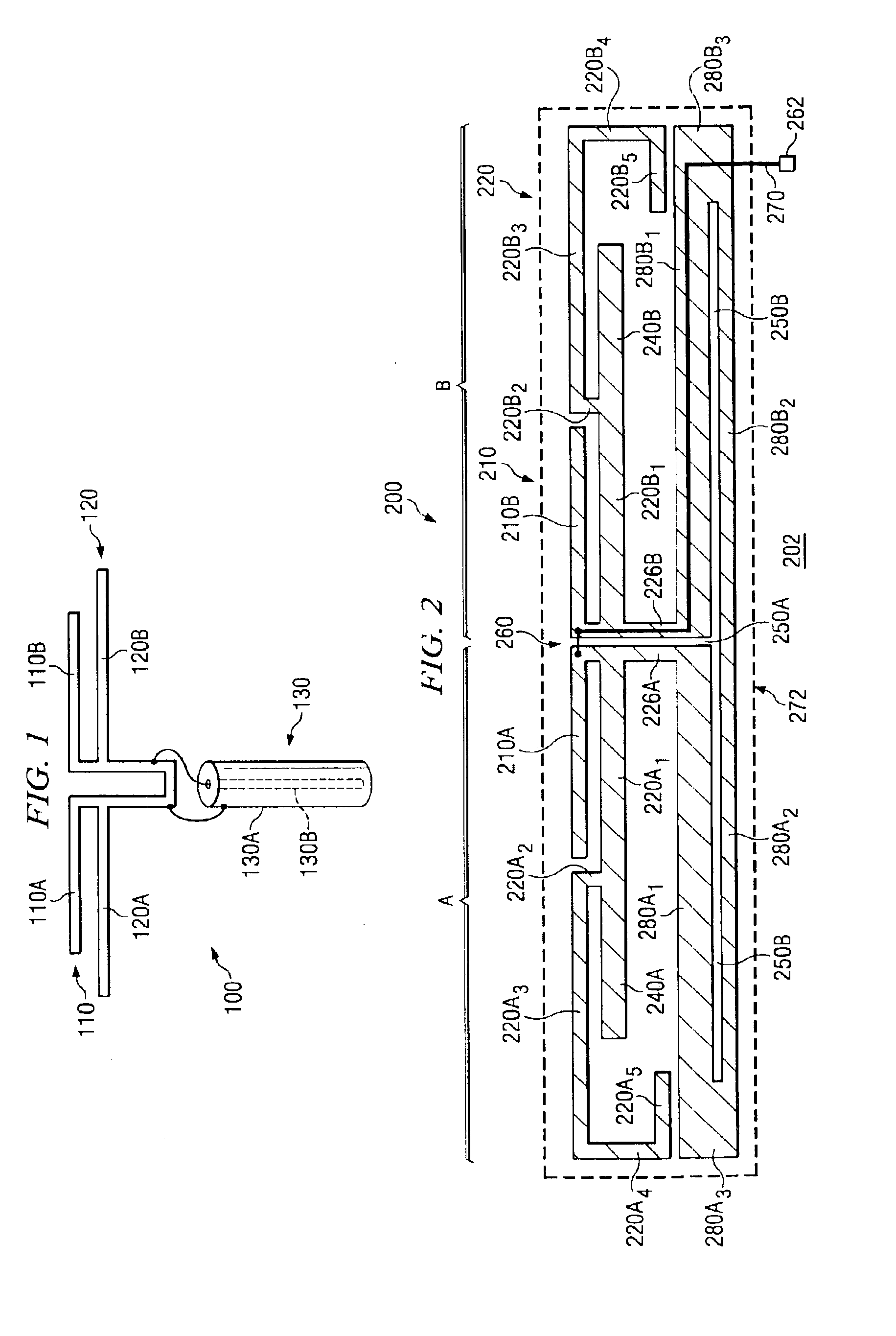
[0005]In accordance with another embodiment of the present invention, an antenna structure comprises a generally rectangular outline having a width, W, and a length, L, and a center axis bisecting the length of the rectangular outline, and a central feed point lying on the center axis of the rectangular outline. The antenna structure includes a first dipole coupled to the central feed point having first and second radiating elements extending opposite one another along the length of the rectangular outline for a total length less than L. The antenna also includes a second dipole coupled to the central feed point having third and fourth radiating elements extending opposite one another along the length of the rectangular outline for a length equal to L. The third and fourth radiating elements further include short perpendicular segments extending along the width of the rectangular outline operable to extend a total length of third and fourth radiating elements to a predetermined desired length. The third and fourth radiating elements generally stay within the rectangular outline. The antenna structure further includes a balun coupled to the central feed point having a length equal to L.
[0006]In accordance with

Problems solved by technology

In these applications, the antenna is typically mounted inside the nose cone of the aircraft where space is severely limited.

Method used


Image

  • Low profile dual frequency dipole antenna structure
  • Low profile dual frequency dipole antenna structure

Examples


Embodiment Construction

[0010]The preferred embodiment of the present invention and its advantages are best understood by referring to FIGS. 1 and 2 of the drawings, like numerals being used for like and corresponding parts of the various drawings.

[0011]A multi-band dipole antenna may be formed by coupling a plurality of parallel dipoles to a common feed system. A center-fed dipole antenna provides a low impedance at the dipole resonant frequency and high impedances at other non-harmonic frequencies. Thus, a plurality of center-fed dipoles may be coupled to a common feed point to form a multi-band dipole antenna system. Each dipole may be constructed to resonate at a particular frequency λ.

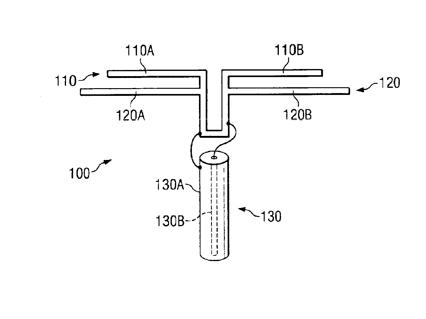
[0012]FIG. 1 is a simplified schematic diagram of a conventional dual-band antenna system 100 having two dipoles. A first dipole antenna 110 having a resonant frequency fo1 of wavelength λ1 is comprised of two radiating elements 110A and 110B of length λ1 / 4, respectively. A second dipole 120 having a resonant frequency o...


PUM


Abstract

An antenna includes a first dipole having first and second stripline radiating elements extending in opposite directions from a central feed point and along a generally rectangular outline of the antenna. The first dipole is operable to be resonant at a first frequency. The antenna also includes a second dipole having third and fourth stripline radiating elements extending in opposite directions from the central feed point and generally parallel to the first and second stripline radiating elements. The third and fourth stripline radiating elements generally follow and stay within the rectangular antenna outline. The second dipole is operable to be resonant at a second frequency. The antenna also includes a stripline balun electrically coupled to the central feed point and extending generally parallel with the first and second dipoles and along the rectangular antenna outline.

Description

TECHNICAL FIELD OF THE INVENTION[0001]This invention relates to antenna structures, and more particularly, to a low profile dipole antenna structure.BACKGROUND OF THE INVENTION[0002]The length of a dipole antenna is related to its operating frequency. A dipole antenna typically has two radiating elements having a common center feed point. The length of the combined dipole radiating elements is typically a multiple of the transmitting or receiving frequency. For example, the dipole radiating elements may have a length that is ¼, ½, or ¾ the wavelength of the radio frequency (RF) energy. In order to operate in two frequency bands, the antenna structure must have two sets of dipole radiating elements with two different lengths.[0003]In certain applications, such as in an instrument landing system (ILS) of an aircraft, a dual-frequency dipole antenna is used to receive the radio frequencies of the glide slope and localizer radio frequency transmissions. In these applications, the antenn...

Claims


Application Information

Patent Timeline
IPC IPC(8): H01Q9/04H01Q21/30H01Q9/16
CPCH01Q9/16H01Q5/371H01Q21/30
Inventor JOY, PHILIPREASONER, HAROLD D.
Owner LOCKHEED MARTIN CORP
Learn More