Structure of a radio-frequency front end

a radio frequency front end and integrated technology, applied in the direction of resonant antennas, substantially flat resonant elements, multi-frequency-changing modulation transference, etc., can solve the problems of small communication apparatus and simplify design, and achieve the effect of reducing transmitter losses, reducing power amplifier design, and reducing the loss of receivers

Inactive Publication Date: 2005-11-01
CANTOR FITZGERALD SECURITIES
View PDF19 Cites 57 Cited by
  • Summary
  • Abstract
  • Description
  • Claims
  • Application Information

AI Technical Summary

Benefits of technology

[0013]An advantage of the invention is that the number of structural elements needed for matching between the RF parts is smaller than in prior-art structures. Another advantage of the invention is that it makes possible a greater sensitivity of receiver than prior art structures. The noise figure and the sensitivity of the receiver branch can be improved by means of internal optimization, for example. A further advantage of the invention is that it makes possible lower losses in the transmitter than prior art structures. For exampl

Problems solved by technology

This leads to smaller communications a

Method used


Image

  • Structure of a radio-frequency front end
  • Structure of a radio-frequency front end
  • Structure of a radio-frequency front end

Examples


Embodiment Construction

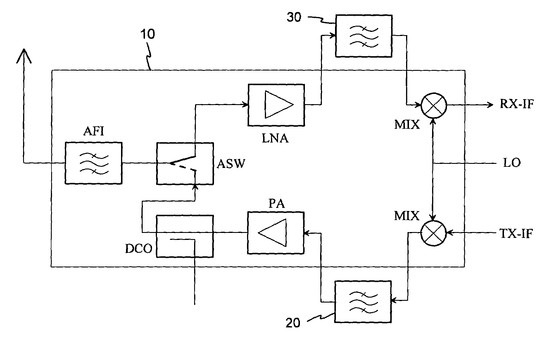
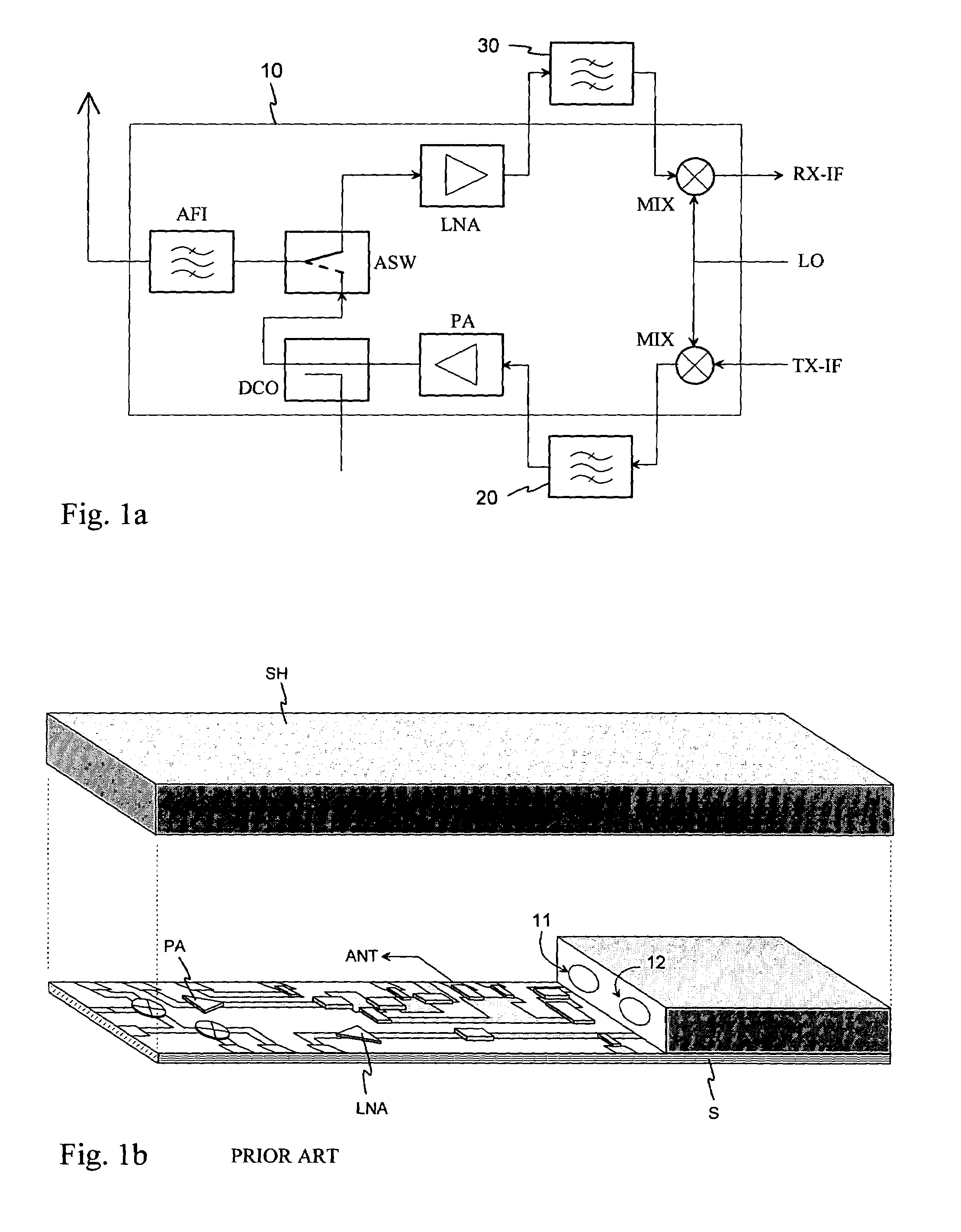
[0021]FIGS. 1a and 1b were already discussed in connection with the description of the prior art.

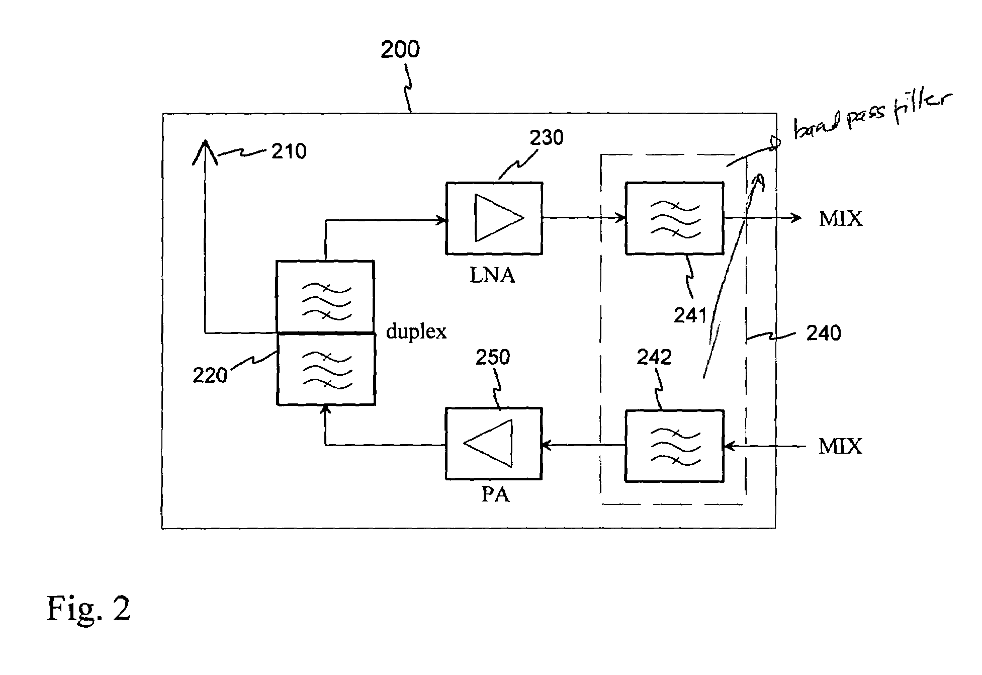
[0022]FIG. 2 shows a block diagram of a possible radio-frequency front end of a communications apparatus. The front end 200 comprises an antenna 210, duplex filter 220, low-noise amplifier 230, bandpass filters 241 and 242, and a power amplifier 250. The antenna is connected to a bi-directional antenna port in the duplex filter 220. The receive port of the duplex filter is connected to the input of the amplifier 230, and the output of the amplifier 230 is connected to the input of the bandpass filter 241. The output of the filter 241 is connected to the receive branch mixer, and the input of the filter 242 is connected to the transmit branch mixer. The output of the filter 242 is connected to the input of the amplifier 250, and the output of the amplifier 250 is connected to the transmit port of the duplex filter 220.

[0023]Next it will be described how a front end 200 according to FIG. 2...


PUM


Abstract

The invention relates to an integrated structure of a radio-frequency front end of a communications apparatus. The antenna of the communications apparatus is constructed on a printed circuit board. To this antenna board (310), on its ground plane side, a second circuit board (321) is attached by means of a rigid protective frame (410), which second circuit board includes the other parts of the radio-frequency front end. Between the parts impedance levels are used that are appropriate from the electrical operation perspective. All said parts together form an integrated component (400) to be located inside the housing of the communications apparatus. The advantage of the invention is that it requires a smaller number of components needed for matching between the RF parts, and makes possible a greater sensitivity of the receiver as well as a better transmitter efficiency than prior art structures.

Description

FIELD OF THE INVENTION[0001]The invention relates to an integrated structure of a radio-frequency front end in a communications apparatus. The front end comprises at least an antenna as well as a radio-frequency amplifier and filter both in the transmit and receive branch.BACKGROUND OF THE INVENTION[0002]Several filters are needed in the radio-frequency part of a bi-directional radio apparatus such as a mobile station. Extra frequency components produced by a mixer as well as extra frequency components produced by a power amplifier have to be removed in the transmit branch. In the receive branch, filters are needed in order to achieve basic selectivity, protect a low-noise pre-amplifier, and to attenuate noise generated by the transmitter on the receive band. In the case of different transmit and receive frequencies a duplex filter is generally used to mutually separate the different directions of transmission. An antenna switch is used in systems in which the transmit and receive f...

Claims


Application Information

Patent Timeline
IPC IPC(8): H01Q1/38H01Q23/00H01Q9/04H01Q1/24H04B1/28H03D7/00H03D7/16
CPCH01Q1/243H01Q1/38H01Q9/0407H01Q23/00H04B1/28H03D7/165
Inventor HAGSTROM, PANU
Owner CANTOR FITZGERALD SECURITIES
Why Eureka
Try Eureka