
Bidirectional distributed amplifier

Inactive Publication Date: 2005-11-01
MOTOROLA SOLUTIONS INC
View PDF5 Cites 29 Cited by
  • Summary
  • Abstract
  • Description
  • Claims
  • Application Information

AI Technical Summary

Problems solved by technology

One drawback of LANs, at least until recent years, was that LAN access was limited to a physical hardware infrastructure.
In either case, providing additional circuitry can increase circuit design complexity and cost, as well as IC manufacturing costs.

Method used


Image

  • Bidirectional distributed amplifier
  • Bidirectional distributed amplifier
  • Bidirectional distributed amplifier

Examples


Embodiment Construction

[0014]The following detailed description is merely exemplary in nature and is not intended to limit the invention or the application and uses of the invention. Furthermore, there is no intention to be bound by any expressed or implied theory presented in the preceding background of the invention or the following detailed description.

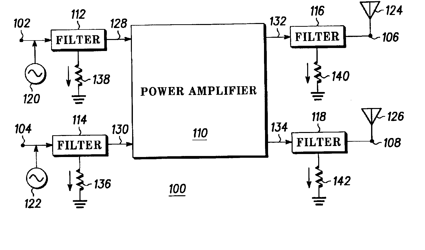
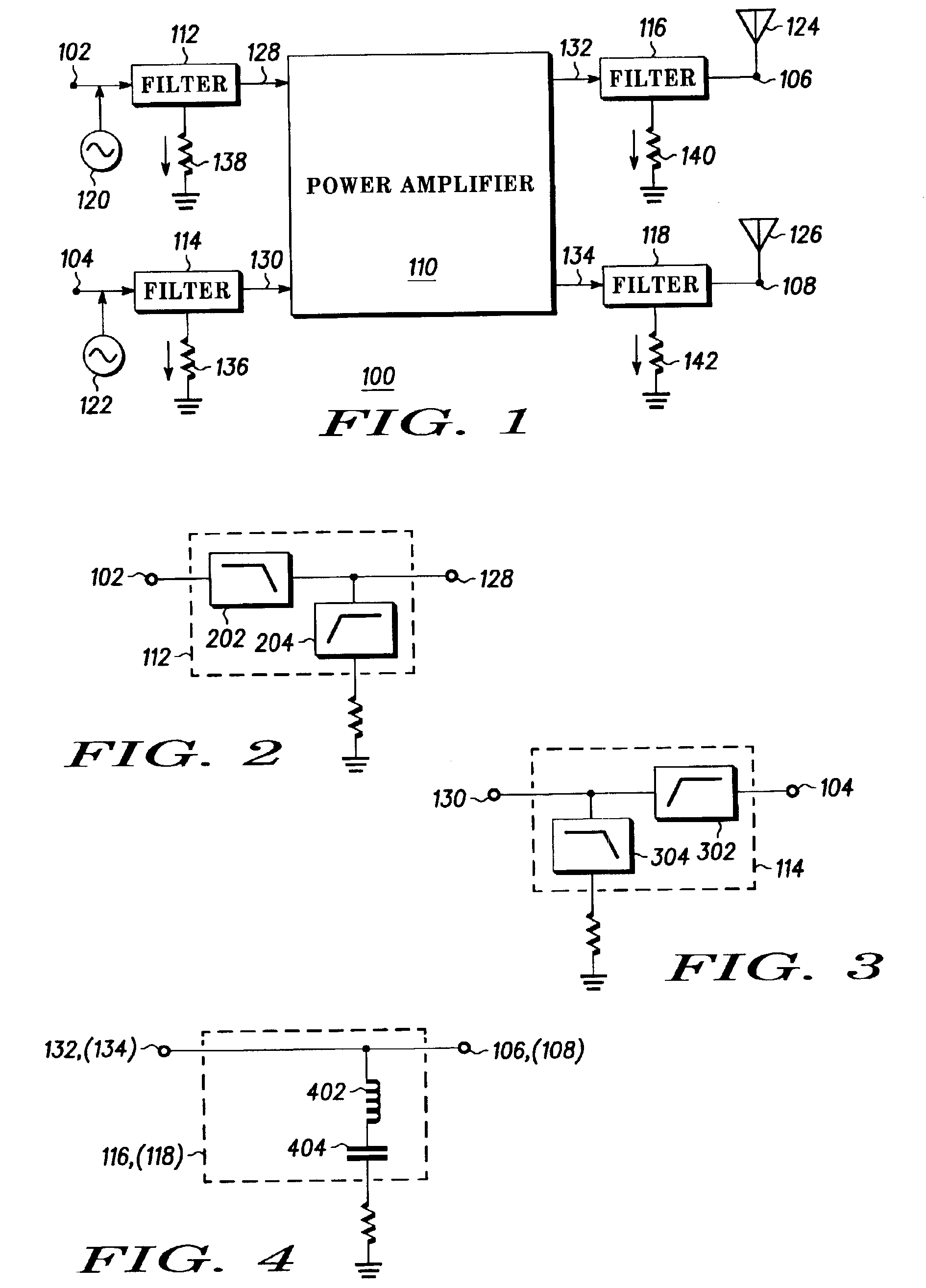
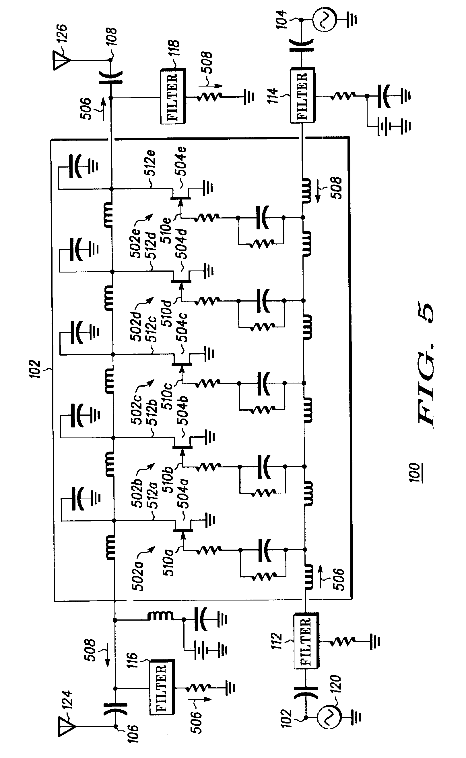
[0015]A functional block diagram of an exemplary bidirectional distributed amplifier circuit is depicted in FIG. 1. The amplifier circuit 100 includes first 102 and second 104 input ports, first 106 and second 108 output ports, a power amplifier 110, and four filter circuits, a first filter circuit 112, a second filter circuit 114, a third filter circuit 116, and a fourth filter circuit 118. The first 102 and second 104 input ports are each adapted receive a signal from a signal source, which may be a modulated signal source. For example, in the embodiment depicted in FIG. 1, the first 102 and second 104 input ports are coupled to a first 120 and a secon...


PUM


Abstract

A bidirectional amplifier circuit includes first and second input ports, first and second output ports, a power amplifier, and first, second, third, and fourth filter circuits. The power amplifier includes at least first and second input terminals and first and second output terminals. The first filter circuit is coupled between the first input port and the power amplifier first input terminal. The second filter circuit is coupled between the second input port and the power amplifier second input terminal. The third filter circuit is coupled between the first output port and the power amplifier first output terminal. The fourth filter circuit is coupled between the second output port and the power amplifier second output terminal. Carrier waves of differing frequencies may be injected into the amplifier circuit first and second input ports, and transmitted from the first and second output ports. The configuration provides broadband operation with flat gain and high efficiency at the frequencies of each of the carrier waves.

Description

FIELD OF THE INVENTION[0001]The present invention generally relates to bidirectional amplifiers and, more particularly, to a bidirectional distributed amplifier that simultaneously amplifies a plurality of frequency bands without implementing any band switching.BACKGROUND OF THE INVENTION[0002]The development of high speed communications protocols, and the hardware to implement these protocols, brought about the capability for numerous computers to communicate with one another over a so-called local area network (LAN). Presently, many organizations have LANs, which allow the organization's employees to communicate with one another, and collaborate on various projects, each from their own computer workstation. One drawback of LANs, at least until recent years, was that LAN access was limited to a physical hardware infrastructure. In other words, users could only connect to a LAN node through some physical hardware, be it a network cable or a telephone land line.[0003]More recently, w...

Claims


Application Information

Patent Timeline
IPC IPC(8): H03G3/04H03G3/10H03F3/14H03F3/04H04M1/00H04B1/38H04B1/10H04M9/00H03F3/60H04BH04B1/04
CPCH03F3/607H04B1/0483
Inventor ZHAO, LEIPAVIO, ANTHONY
Owner MOTOROLA SOLUTIONS INC
Learn More