
Method and apparatus for tuning compensation parameters

Inactive Publication Date: 2005-11-01
SIEMENS ENERGY & AUTOMATION INC
View PDF21 Cites 53 Cited by
  • Summary
  • Abstract
  • Description
  • Claims
  • Application Information

AI Technical Summary

Benefits of technology

[0011]Accordingly, the present invention is directed to t

Problems solved by technology

In practice, it is difficult, if not impossible, to achieve zero following error during motion of the axis if only feedback control is utilized.
However, in the case of cut direction changes or in complex contouring, following errors can cause the machined path to deviate from the desired path resulting in a “contour error.”
Typically, the magnitude of the contour error increases as the feedrate and / or path curvature increases.
In addition to following errors, disturbance forces, such as Coulomb friction, may also cause the machine to deviate from the desired path.
For example, manual tuning took a considerable amount of time, and often provided less than accurate estimates.
In addition, there was not a reliable way of determining whether the model developed from the manual calculations accurately described the actual system dynamics.
Furthermore, when test movements and measurements were used, such as when deriving a Coulomb friction gain, there was no way of determining whether the test sufficiently “excited” the axis by moving it through enough modes of operation (e.g., enough different velocities, accelerations, and position changes.)
In addition, such manual testing procedures did not provide a way of automatically determining an optimum excitation program (i.e., test motion) for the axis based upon user-enterable operating parameters.
However, the derivation of feedforward parameters does not appear to be disclosed, nor does the reference disclose the computation of any confidence factors for indicating the accuracy of the derived parameters.
Also, the reference does not appear to disclose the need for predetermined motion for computing the values, or any method of computing such a motion.

Method used


Image

  • Method and apparatus for tuning compensation parameters
  • Method and apparatus for tuning compensation parameters
  • Method and apparatus for tuning compensation parameters

Examples


Embodiment Construction

I. Exemplary Embodiment of Feedforward Control System

A. Continuous Time Model

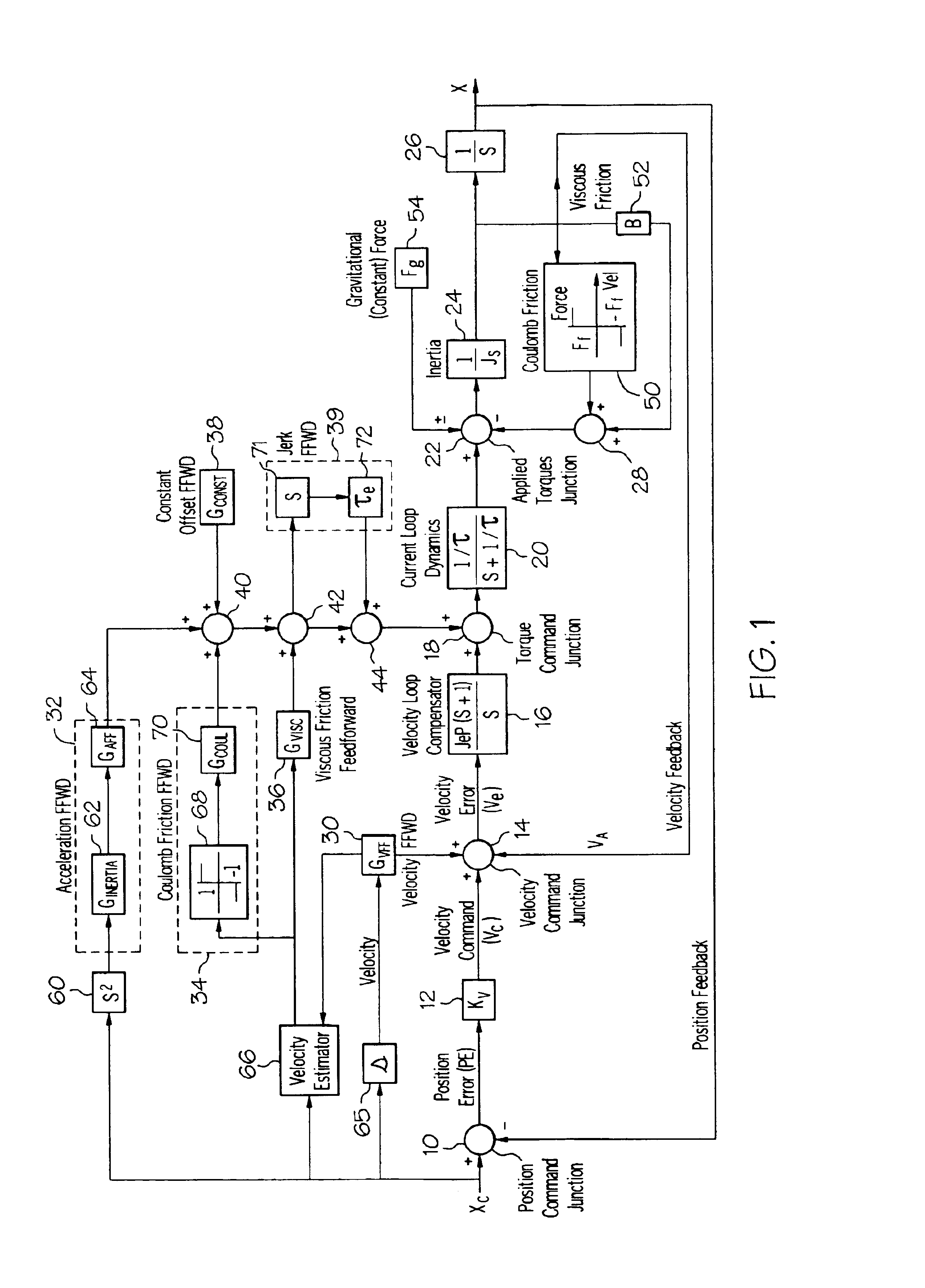
[0034]Referring now to the drawings in detail, FIG. 1 is a block diagram illustrating a continuous time model of an exemplary integrated feedforward control system having feedforward gains which are automatically tuned, according to one aspect of the present invention. The figure illustrates an exemplary model for implementing feedforward to compensate for various system dynamics in a motion control system, where s in the figure represents differentiating, and l / s represents integrating, as is known in the art. The model includes compensation for Coulomb and viscous friction, gravitational effects, and inertial effects. The model could be implemented using analog circuits, and, as can be understood, concepts which apply to this embodiment are discussed for further understanding of the invention, as these concepts may be applicable to other embodiments discussed herein. Also, it should be understood that whi...


PUM


Abstract

A method and apparatus for tuning a feedforward compensation parameter in a motion control system is provided. According to one such embodiment, the method includes the acts of determining an initial value of a feedforward compensation parameter and commanding an initial movement of an actuator according to a test motion routine (wherein the initial value of the parameter is used in the control of the actuator). Error associated with the initial movement is determined. A potential value of the feedforward compensation parameter is determined. A movement of the actuator is commanded according to the test motion routine (wherein the potential value of the parameter is used in the control of the actuator) and error associated with the movement is determined. The errors associated with the movements are compared and, based on the act of comparing the errors, one of the values is selected as a current best value. In a further embodiment, such acts are repeated until the current best value is an optimum value.

Description

[0001]This application is a continuation-in-part of application Ser. No. 09 / 293,096, which was filed on Apr. 16, 1999, now U.S. Pat. No. 6,470,225 the entire disclosure of which is hereby incorporated by reference.TECHNICAL FIELD[0002]The present invention relates to tuning compensation parameters in a motion control system, and, more particularly, in one embodiment, to a method and apparatus which iteratively tunes a parameter which compensates for time-shift relationships in a motion control system.BACKGROUND OF THE INVENTION[0003]Traditional machine tool position control systems are designed with feedback control in which “following error” (the difference between the actual and desired positions) produces a command which is delivered to a velocity control loop for driving an actuator connected to a movable member. The actuator and / or connected movable member are sometimes referred to as an “axis” of the machine tool or device having the movable member. In practice, it is difficul...

Claims


Application Information

Patent Timeline
IPC IPC(8): G05B11/42G05B13/04G05B11/28G05B11/01
CPCG05B11/28G05B11/42G05B13/042
Inventor YUTKOWITZ, STEPHEN J.
Owner SIEMENS ENERGY & AUTOMATION INC
Learn More