Boiling heat transfer torpedo

a heat transfer and torpedo technology, applied in special-purpose vessels, vessel construction, transportation and packaging, etc., can solve the problems of limiting the performance of undersea vehicles such as torpedoes, limiting the speed and range of torpedoes, and creating drag

Inactive Publication Date: 2005-11-08
THE UNITED STATES OF AMERICA AS REPRESENTED BY THE SECRETARY OF THE NAVY
View PDF6 Cites 17 Cited by
  • Summary
  • Abstract
  • Description
  • Claims
  • Application Information

AI Technical Summary

Benefits of technology

[0007]The first object of the invention is to provide a system for reducing drag and increasing propulsion efficiency of an undersea vehicle, such as a torpedo.
[0008]Another object is to provide a system for reducing drag and increasing propulsion efficiency of a torpedo with a gas / vapor cavity created and maintained during a torpedo run.
[0009]Another object is to provide a system for reducing drag and increasing propulsion efficiency on a torpedo using ventilation gas, gas recycling, and waste heat from a propulsion engine to create and maintain a controllable, stable gas / vapor cavity.

Problems solved by technology

Undersea vehicles, such as torpedoes, are restricted in speed and range by the size of their power plants and amount of fuel they carry.
Another significant factor limiting performance is the amount of drag created as the torpedoes go through water to their targets.

Method used


Image

  • Boiling heat transfer torpedo
  • Boiling heat transfer torpedo
  • Boiling heat transfer torpedo

Examples


Embodiment Construction

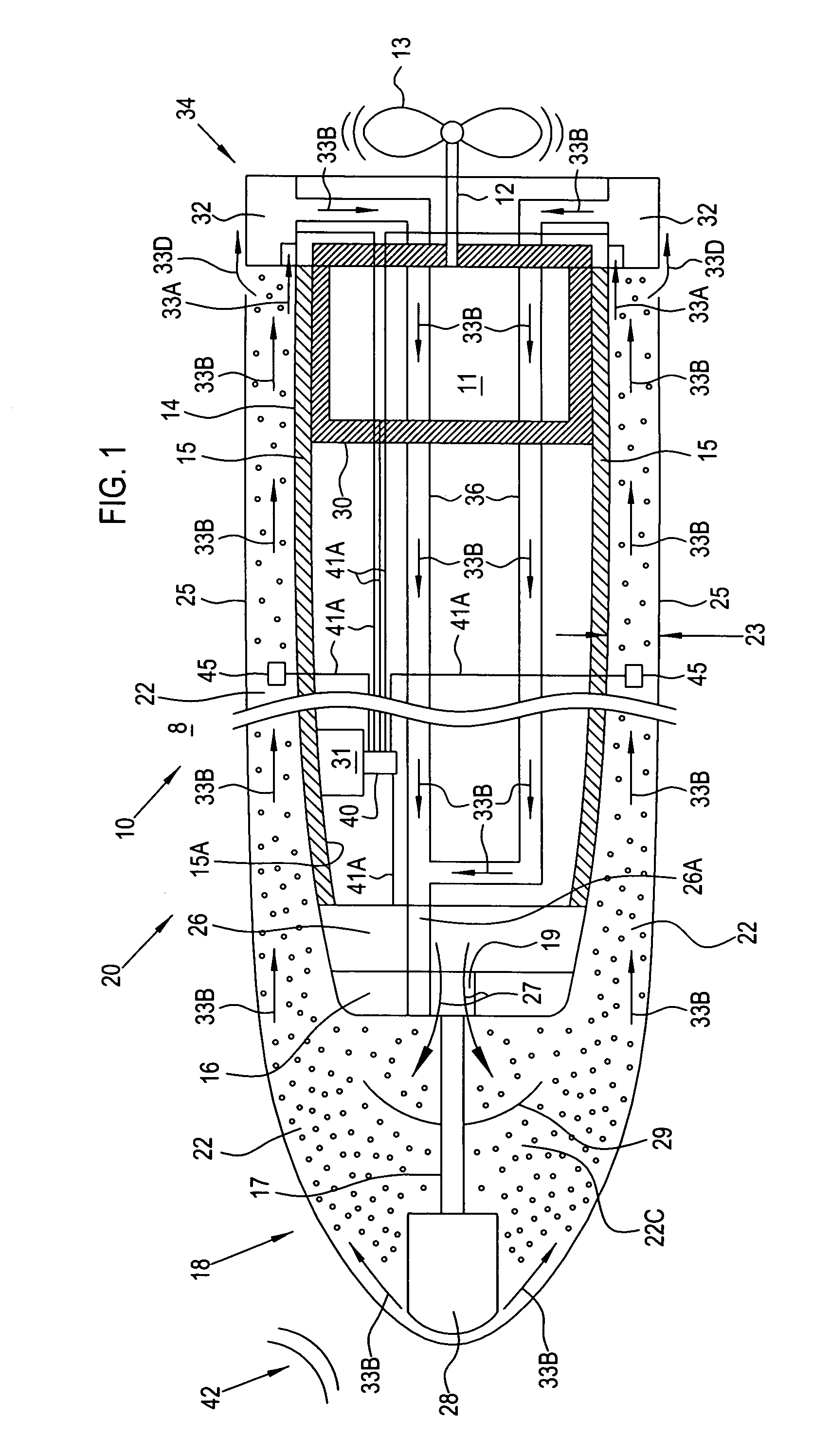
[0020]Referring to FIG. 1 of the drawings, a torpedo 10 has an internal thermal engine or motor 11 connected by a shaft 12 to one or more propellers 13 to propel torpedo 10 through ambient water 8 to a distant target. Engine 11 can be any of many well known proven designs that creates sufficient power to rotate interconnected propellers 13 for propulsive thrust and generates considerable amounts of waste heat as a by-product of operation. Engine 11 could also be a rocket or jet engine that produces significant waste heat. This waste heat is effectively coupled by heat transfer-ventilation system of the invention to an outer surface 14 of hull 15 of torpedo 10 to help create a cavity 22 to reduce drag between torpedo 10 and ambient water 8.

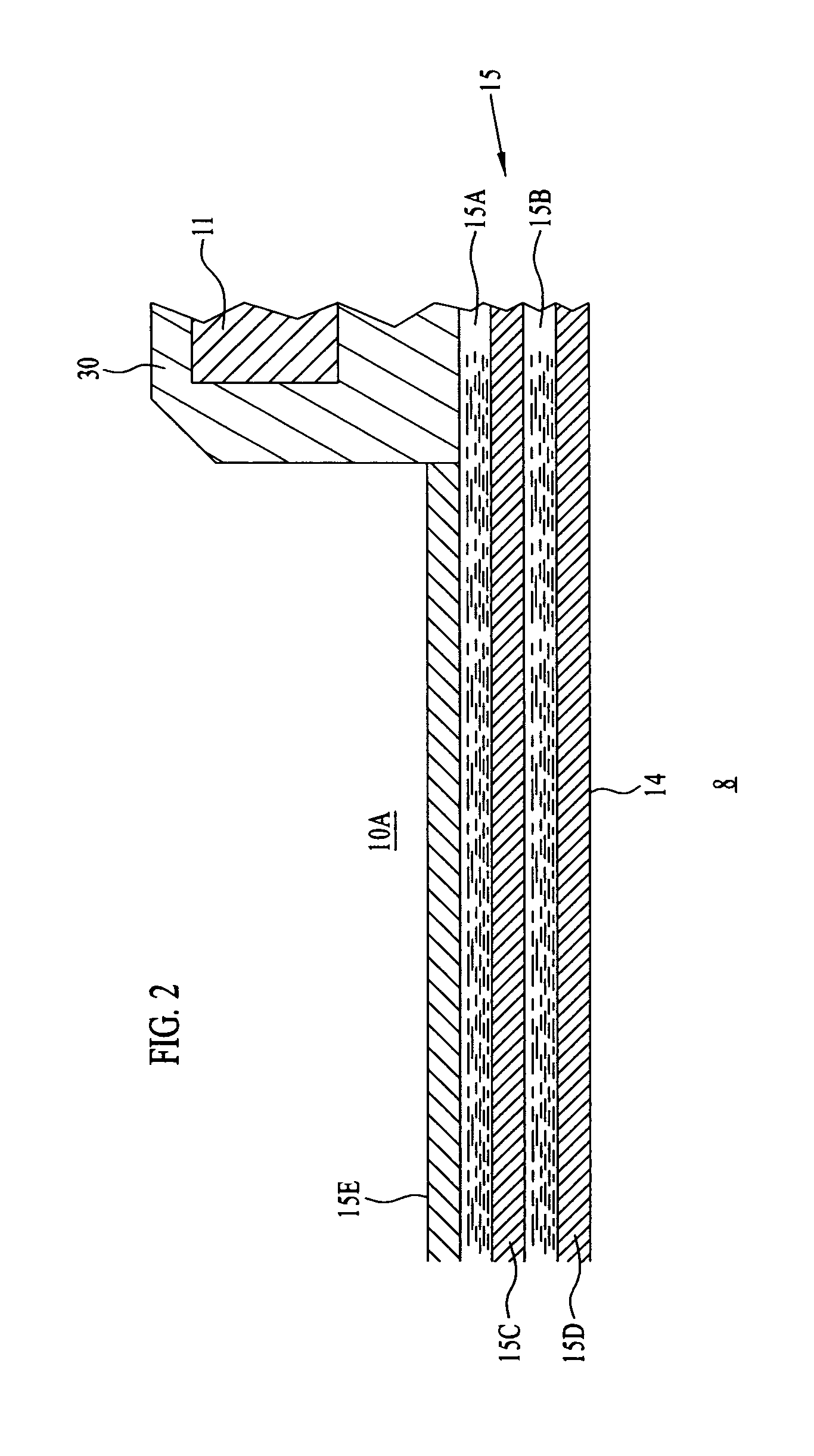
[0021]Referring also to FIG. 2, hull 15 can be made of layers 15A, 15B, of high heat capacity liquid or metal that are sandwiched within matrix layers 15C, 15D of highly conductive material. Hull 15 has an insulating layer 15E for thermal shielding...


PUM


Abstract

A system has a source of gas venting gas at a nose portion of the vehicle to create a gas / vapor cavity on the nose portion and an adjacent hull of the vehicle. A thermal engine propelling the vehicle through ambient water creates waste heat for heating the hull to raise the temperature of the gas / vapor cavity extending over it. A pump aft on the vehicle recirculates a portion of the gas / vapor cavity as recirculated gas to the nose portion. The velocity of the recirculated gas of the gas / vapor cavity is controlled by the pump to be virtually the same as the relative flow rate of the ambient water along an interface boundary between the gas / vapor cavity and the ambient water.

Description

STATEMENT OF GOVERNMENT INTEREST[0001]The invention described herein may be manufactured and used by or for the Government of the United States of America for governmental purposes without the payment of any royalties thereon or therefor.BACKGROUND OF THE INVENTION[0002](1) Field of the Invention[0003]The present invention relates generally to a system for increasing the performance of undersea vehicles. More particularly, this invention relates to a system for a torpedo that creates and maintains a vapor cavity to reduce drag and increase propulsion efficiency.[0004](2) Description of the Prior Art[0005]Undersea vehicles, such as torpedoes, are restricted in speed and range by the size of their power plants and amount of fuel they carry. Another significant factor limiting performance is the amount of drag created as the torpedoes go through water to their targets. Considerable research by designers of torpedoes to reduce drag is ongoing, but acceptable results are still being soug...

Claims


Application Information

Patent Timeline
Patent Type & Authority Patents(United States)
IPC IPC(8): B63B1/00B63B1/34F42B19/12
CPCF42B19/125
Inventor KUKLINSKI, ROBERT
Owner THE UNITED STATES OF AMERICA AS REPRESENTED BY THE SECRETARY OF THE NAVY
Why Eureka
Try Eureka