Power tool

a technology of power tools and cooling devices, applied in the field of power tools, can solve the problems of reducing the useful working affecting the service life of the operative element, and the cooling method is not suitable for all types of power tools, so as to improve the cooling system of the working zone

Inactive Publication Date: 2005-11-08
DEMAIN TECH
View PDF17 Cites 30 Cited by
  • Summary
  • Abstract
  • Description
  • Claims
  • Application Information

AI Technical Summary

Problems solved by technology

Power tools of the foregoing kind tend to develop high temperatures at the work face, and that has the disadvantage of reducing the useful working life of the operative element (e.g., cutting tool, grinding wheel, etc.).
That method of cooling is not suited for all types of power tools, and is particularly not suited for use with portable hand-held power tools.

Method used


Image

  • Power tool
  • Power tool
  • Power tool

Examples


Embodiment Construction

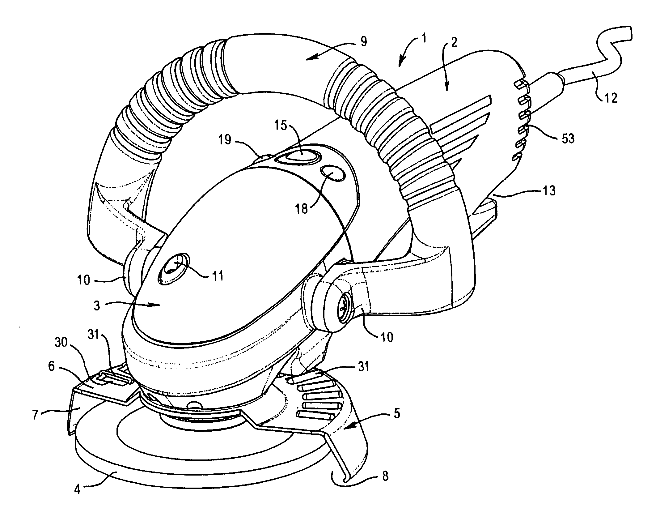
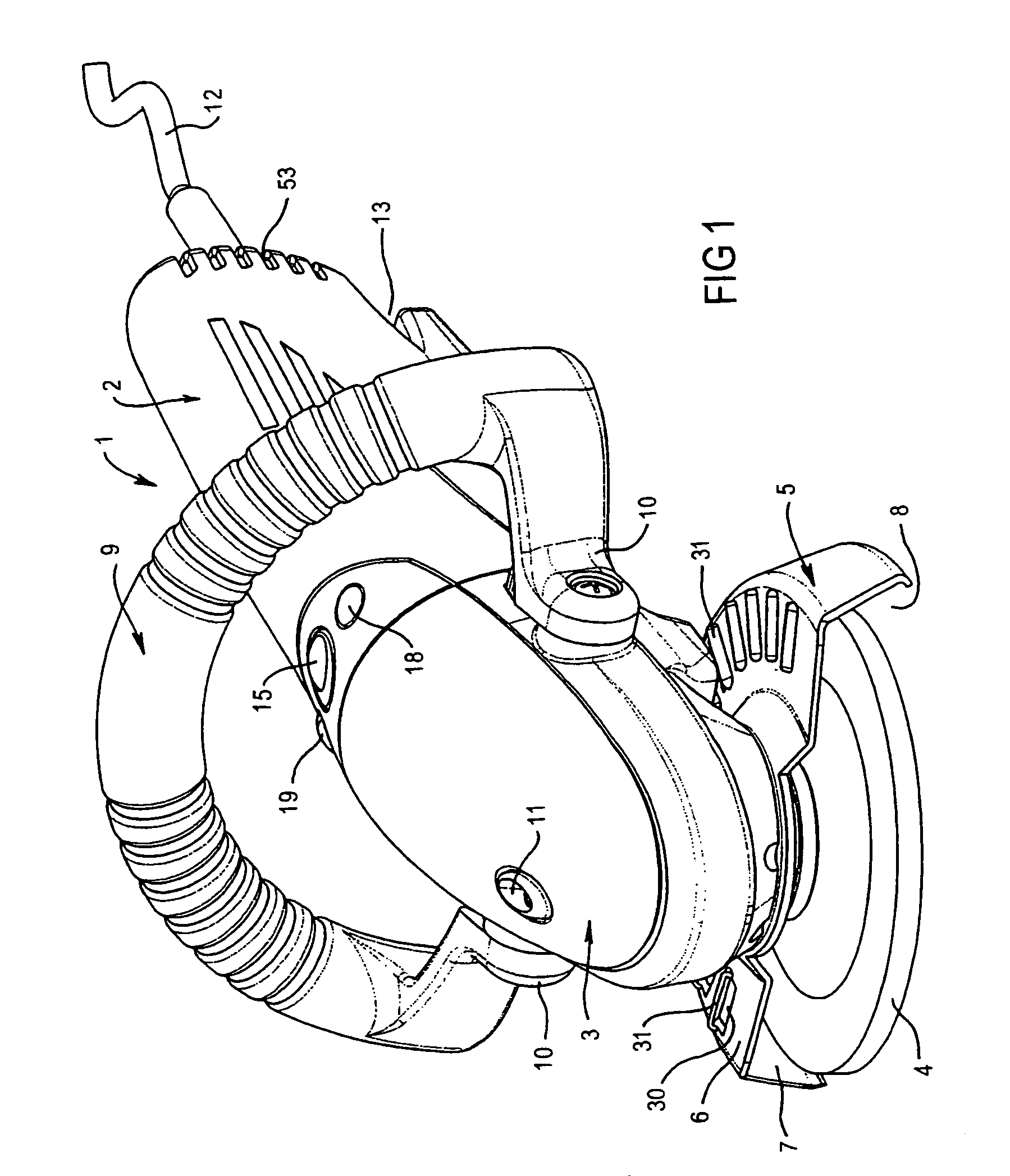
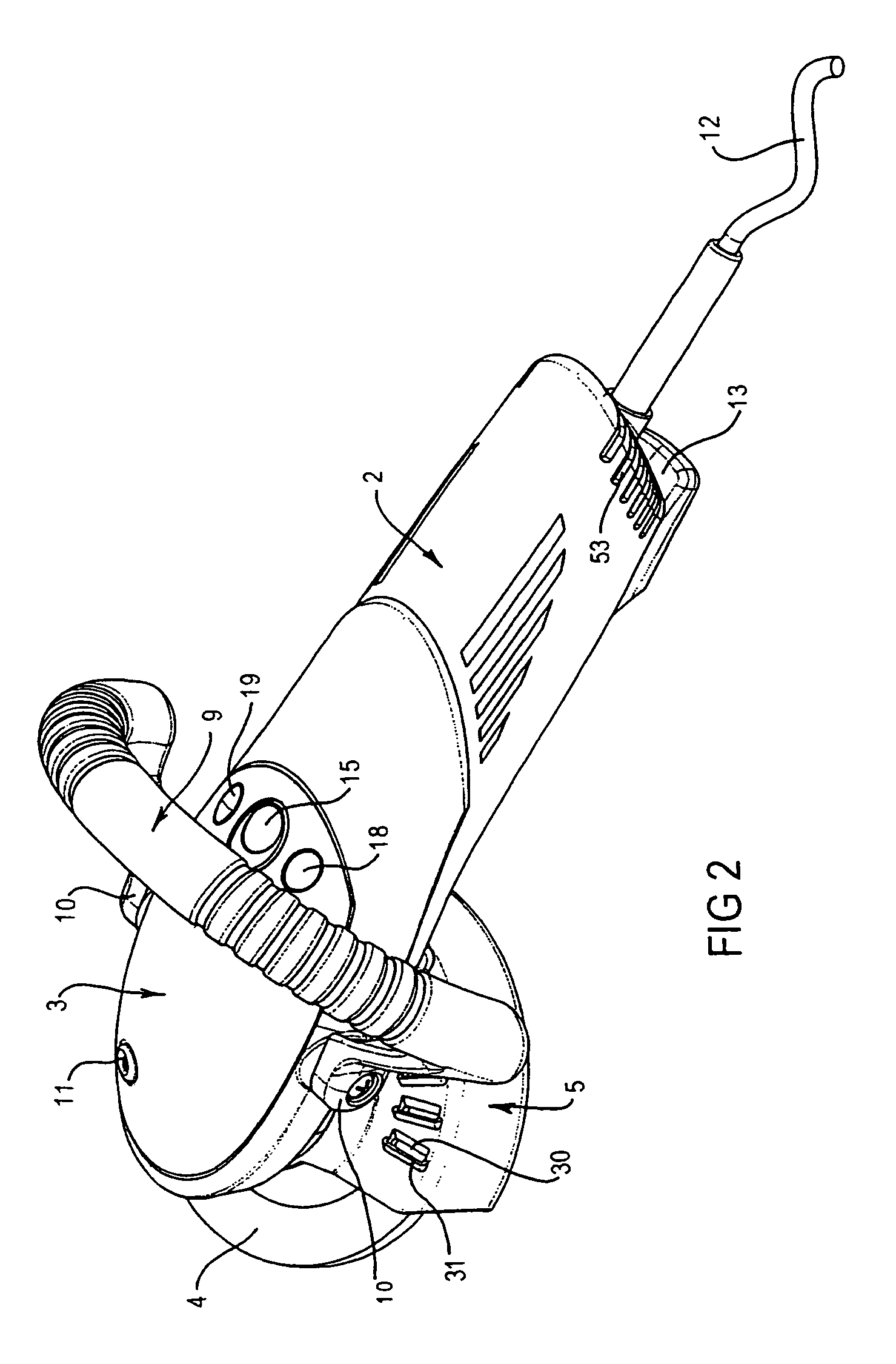
[0035]FIGS. 1 to 4 show an example hand-held tool incorporating one embodiment of the invention. That example tool is an angle-grinder, and it is to be understood that the invention can be applied to other types of tools, whether they be hand-held, bench mounted, or free standing.

[0036]The tool 1 shown by FIGS. 1 to 4 includes a body portion 2 and a head portion 3. An operative element in the form of a rotatable grinding disc 4 is carried by the head portion 3, and a protective guard or shroud 5 overlies and surrounds a substantial part of the disc 4. In that regard, a plate section 6 of the shroud 5 overlies the upper surface of the disc 4, and a skirt 7 of the shroud 5 extends around the periphery of the disc 4. An opening 8 is provided at the front of the shroud 5 to enable engagement between the disc 4 and a work piece (not shown). The disc 4 is arranged for rotation about an axis extending transverse to the longitudinal axis of the tool 1.

[0037]It is preferred that the shroud 5...


PUM


Abstract

This invention relates to a power tool (1) including an operative element (4) for treating a work piece. The power tool (1) defines an air passageway and includes propelling means (20) operative to induce air to flow through the passageway. The passageway direct the induced air over the power tool's motor (14) to cool the motor (14). The air is exhausted from the tool (1) by exhaust means onto the operative element (4) and a worked face of the work piece. This cools the operative clement (4) which prolongs its working life. Furthermore, the exhausted air facilitates removal of swarf from the worked face.

Description

[0001]This application is a continuation of PCT International Application No. PCT / AU01 / 00254 filed 9 Mar. 2001, which claims priority of Australian Patent Application No. PQ 6188 filed 10 Mar. 2000.FIELD OF THE INVENTION[0002]The present invention relates to power tools, and is applicable to such tools that are hand-held, bench mounted, or free standing. The invention is particularly, but not exclusively, concerned with such tools that treat a work piece by, a cutting, grinding, or other material removal, process.RELATED APPLICATIONS[0003]The present application is related to the subject matter of provisional patent application entitled “Power Tool Controller” filed on 10, Mar. 2000 by the present applicant, the subject matter of which is incorporated herein by cross-reference.BACKGROUND OF THE INVENTION[0004]It will be convenient to hereinafter describe the invention with particular reference to an example power tool of the electrically operated hand-held type, but it needs to be u...

Claims


Application Information

Patent Timeline
Patent Type & Authority Patents(United States)
IPC IPC(8): B23Q11/00B24B23/02B24B23/00B24B55/00B24B55/02B25F5/00B25F5/02
CPCB23Q11/005B24B23/005B24B23/026B24B23/028B24B55/02B25F5/00B25F5/008B25F5/02B25F5/026
Inventor FRASER, MARC ANTHONYBAYLY, PETER KINGSLEY
Owner DEMAIN TECH
Why Eureka
Try Eureka