Rearview mirror constructed for efficient assembly

a rearview mirror and efficient technology, applied in the field of rearview mirrors, can solve the problems of distortion of reflected images, occupying considerable space, and increasing the order of mirrors

Inactive Publication Date: 2005-11-08
GENTEX CORP
View PDF95 Cites 116 Cited by
  • Summary
  • Abstract
  • Description
  • Claims
  • Application Information

AI Technical Summary

Benefits of technology

[0010]In one aspect of the present invention, a mirror assembly includes an electrochromic mirror including a first connector operably connected to the electrochromic mirror, and an electrically-operated second component associated with the electrochromic mirror that includes a second connector operably connected to the electrically-operated second component. A primary wire bundle extends from and is configured to communicate power to the electrochromic mirror and to the electrically-operated second component, the primary wire bundle including a main connector. The first connector engages and is electrically connected to the main connector, and the second connector engages and is electrically connected to one of the main connector and the first connector. By this arrangement, the primary wire bundle is configured to communicate power to the electrochromic mirror and to the second component in a manner minimizing the number of electrical connections and connectors necessary during assembly to a mirror housing.
[0011]In another aspect of the present invention, a rearview mirror assembly for a vehicle includes a housing, and a mirror subassembly positioned in the housing and including a panel-shaped carrier. First and second electrically-operated components are associated with the mirror subassembly and include first and second connectors, respectively. A primary wire bundle extends from and is configured to communicate power to the first and second components, the primary wire bundle including a main connector. The first and second connectors engage and are electrically directly connected to the main connector. By this arrangement, the primary wire bundle and the first and second connectors are configured to communicate power to the first and second components in a manner minimizing the number of electrical connections necessary during assembly to a vehicle.

Problems solved by technology

Routing of wires to support the various electrical components can be a logistic nightmare, and further, even if routed carefully and consistently, can take up considerable space.
Another problem caused by multiple components in a mirror is that the mirror becomes thicker in order to make room for the wiring and connectors and also heavier due to the connectors, wires, and related support structure.
Weight, even in small amounts, is an issue in electrochromic mirror subassemblies because these mirrors use a pair of glass elements with an electrochromic layer therebetween.
Vehicle manufacturers have hesitated going below this thickness because the glass elements will bend too easily, resulting in distortion of the reflected images.
This can cause several difficulties and complications in a mirror.
For example, the light-generating turn signal device adds weight and takes up space, such that the resulting assembly is potentially heavier and larger than mirror assemblies not having this feature.
Further, the turn signal device requires additional wiring within the mirror assembly, which can cause assembly concerns related to electrical connections and positioning of connectors, as discussed above.
Further, a defective turn signal device non-removably attached to an electrochromic mirror subassembly can result in scrapping out and throwing away a “good” electrochromic mirror subassembly, which is a relatively expensive portion of the overall assembly at that same point in time.
One reason is because, if the turn signal device came loose in an exterior mirror assembly, dirt and light-blocking matter would soon cover the turn signal device, rendering it ineffective.
Also, it could rattle and cause other problems.
However, as the resilient fingers are flexed to engage and then do engage the adjustable mount, the glass-supporting area around the fingers is distorted.
This can be a problem since, if the glass is less than about 2.2-mm thick and the carrier thickness is also minimized for reduced weight, the distortion of the glass-supporting area can read through to the glass, causing noticeable and objectionable distortions in the reflected images.
Distortion of the glass-supporting area can be reduced by making the fingers flimsier and not as stiff, however this would result in a reduced retention force and less reliable connection of the electrochromic mirror subassembly to the power pack.
This, however, adds weight and takes up considerable space if the reinforcement webs are made large enough to do an adequate job.
Further, testing has shown that it is not a solution to this problem to merely add a few random reinforcement webs, since very minor bending in a direction perpendicular to the glass elements of the mirror subassembly in any localized area can result in objectionable glass distortions, especially with glass elements at or under 1.6-mm thickness.
However, pulls and slides are expensive to build into a die and to maintain, and can result in increased scrap.

Method used


Image

  • Rearview mirror constructed for efficient assembly
  • Rearview mirror constructed for efficient assembly
  • Rearview mirror constructed for efficient assembly

Examples


Embodiment Construction

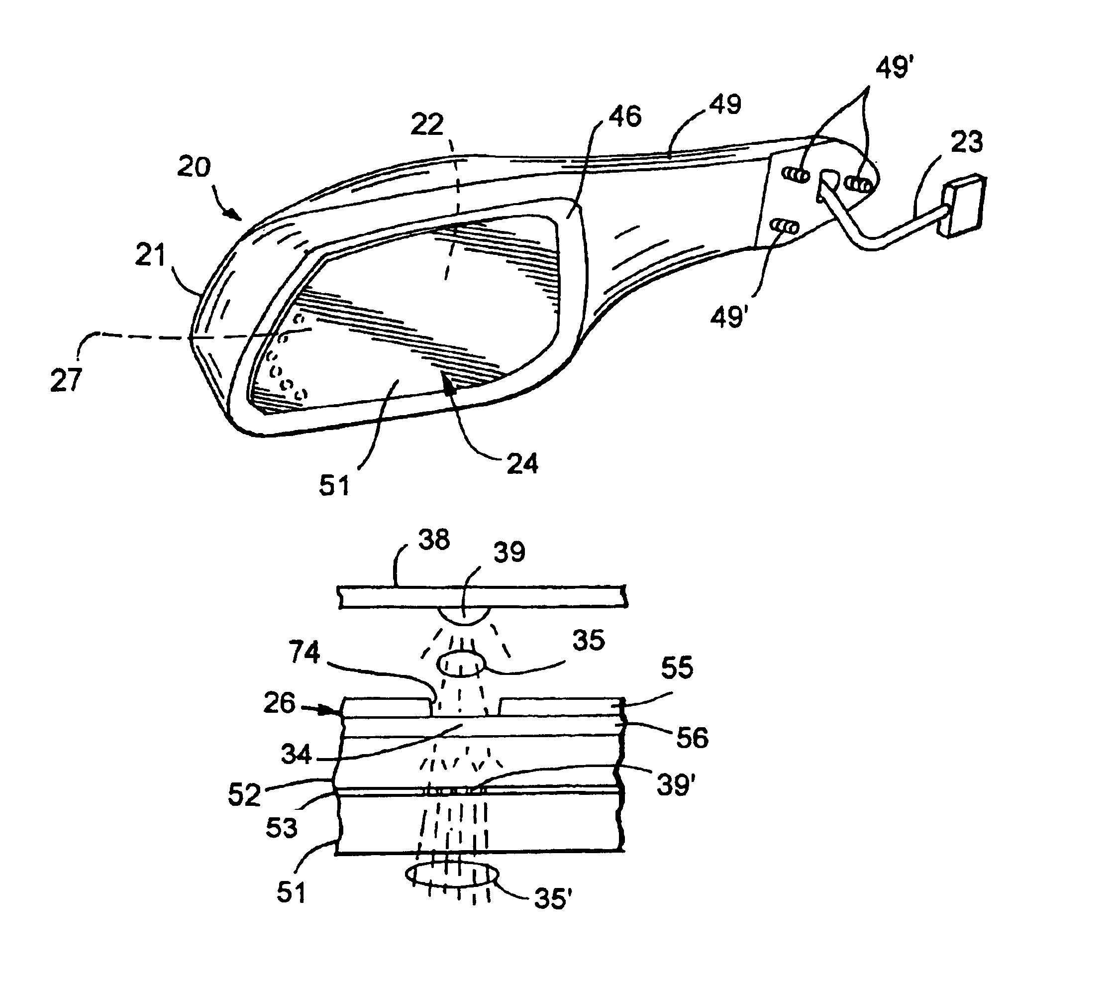
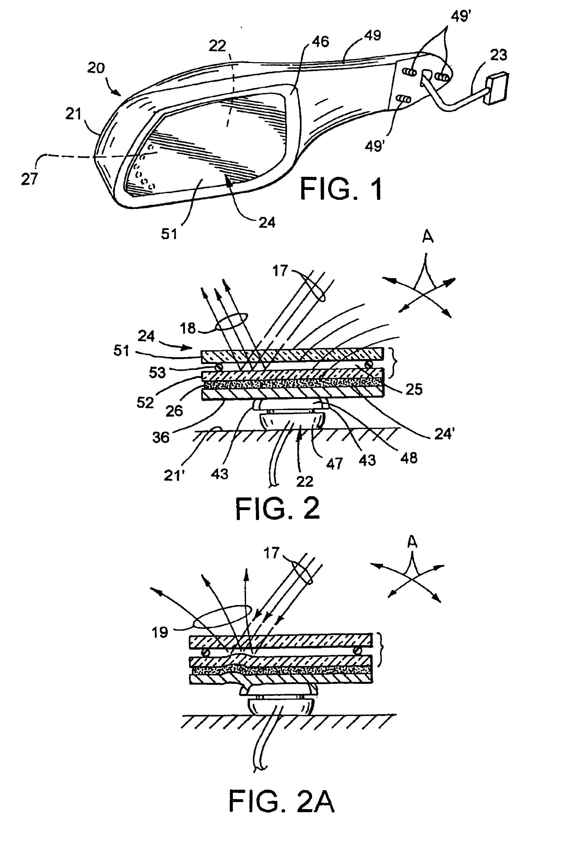
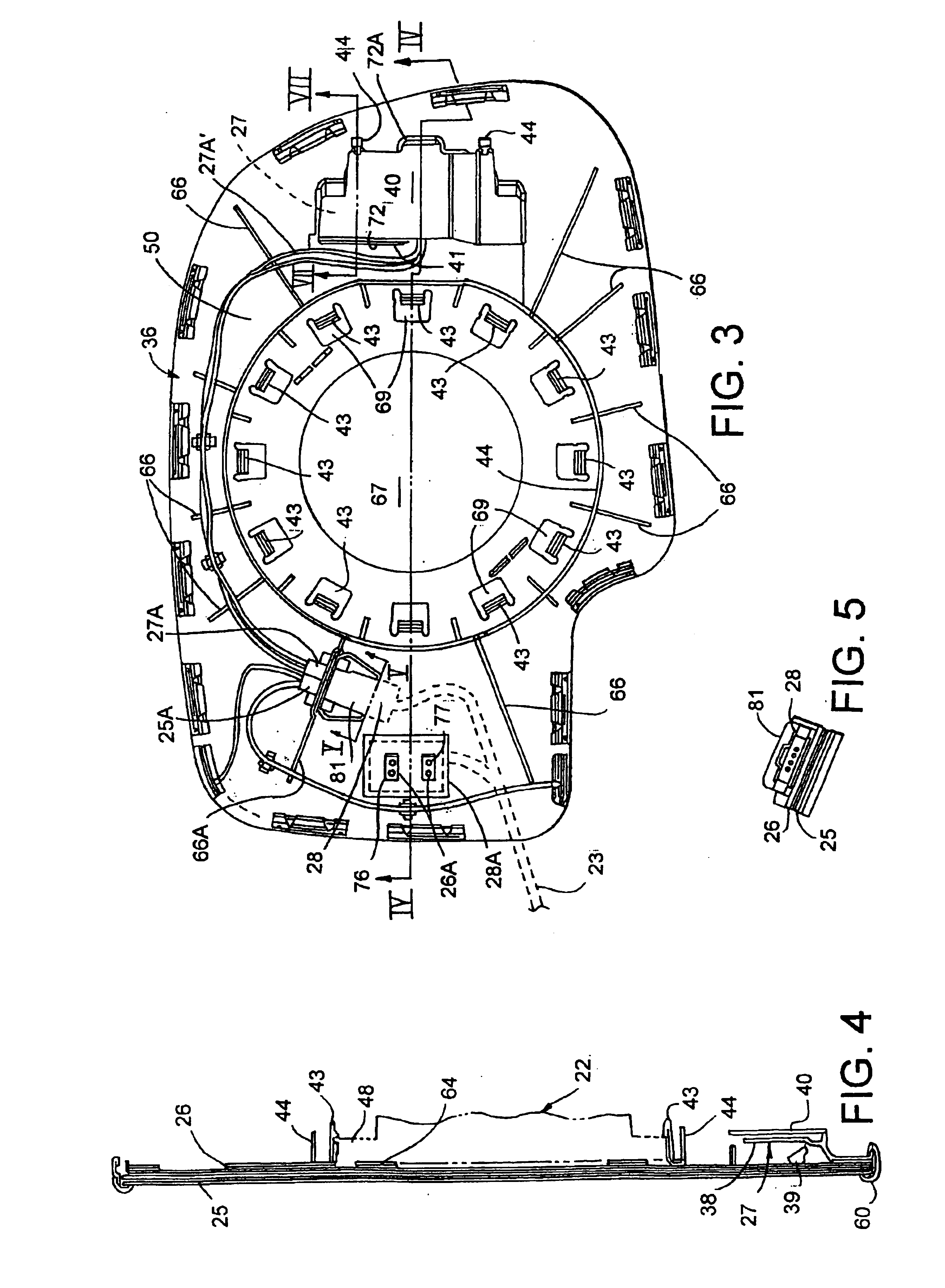
[0046]The illustrated mirror assembly 20 (FIG. 1) includes a housing 21, an angular electrically-powered adjustment mechanism 22 (called a “power pack” herein) (FIG. 2) supported in and attached to a wall 21′ in the housing 21, and main wiring bundle 23 (FIG. 1) for powering and controlling the power pack 22 and the other components in the mirror assembly 20. An electrochromic mirror subassembly 24 (FIG. 2) includes a carrier 36 snappingly attached to a multi-angularly-adjustable plate 48 on the power pack 22 in a manner that minimizes stress on the glass elements of the mirror subassembly 24, as described below. The present mirror assembly 20 is designed to prevent the problem illustrated in FIG. 2A, where resilient fingers on the carrier are stressed and have caused a deformation on the glass elements of the mirror subassembly, resulting in unacceptable distortion of reflected images, as represented by non-parallel reflected light beams 19. (Compare with FIG. 2, where three light ...


PUM

PropertyMeasurementUnit
forceaaaaaaaaaa
electrochromicaaaaaaaaaa
areaaaaaaaaaaa

Abstract

A mirror assembly includes a housing, an angularly adjustable power pack, wires for supplying power and mirror angle control, an electrochromic mirror subassembly including a heater, and a turn signal device. The components include individual connectors that plug into a multi-prong connector on the bundle of wires, or that piggyback into each other. Optionally, the heater incorporates an internal wire with end connectors for communicating power to opposite sides of the heater, and also includes layers of light-transmitting / diffusing material for diffusing light passing from the turn signal device through the diffusing material. A printed circuit board fits into a pocket in the panel-shaped carrier, and an integral retainer releasably secures the printed circuit board. The power pack is attached to the carrier via a ring of resilient fingers, and a continuous hoop flange prevents distortion of the carrier and in turn of the glass elements in the mirror subassembly.

Description

CROSS REFERENCE TO RELATED APPLICATION[0001]This application is a continuation of U.S. Pat. No. 6,650,457 entitled REARVIEW MIRROR CONSTRUCTED FOR EFFICIENT ASSEMBLY, the entire disclosures of which is incorporated herein by reference.BACKGROUND OF THE INVENTION[0002]The present invention relates to a rearview mirror for vehicles constructed for efficient and optimal assembly, including components shaped for efficient and low-scrap molding and manufacture, components having features integrated into them to reduce the overall number of parts, pieces, and total weight, and components arranged to facilitate mechanical assembly and physical layout as well as electrical interconnection and repair of electrical circuits.[0003]Modern vehicle mirrors often include numerous electrical components that must be powered and also controlled. For example, the electrical components of one proposed high-end exterior mirror will include an electrochromic image-darkening mirror subassembly and control...

Claims


Application Information

Patent Timeline
Patent Type & Authority Patents(United States)
IPC IPC(8): B60R1/062B60R1/07B60R1/08H05K1/18H05K3/00H05K1/02B60Q1/26
CPCB60Q1/2665B60R1/0602B60R1/07B60R1/072B60R1/088B60R1/1207G02B5/08H05K1/18H05K1/189B60R2001/1215H05K1/02H05K3/0058H05K2201/09072H05K2201/09081H05K2201/10106H05K2201/10484
Inventor BUSSCHER, BRADLEY L.NORTHMAN, BRADLEY L.YPMA, KENTON J.BEUTE, RANDALL J.ROBERTS, JOHN K.JORDAN, WAYNE M.DENAVE, EDWARD L.BOSTWICK, DANIEL J.BRAUN, RANDALL S.BOSCH, GREGORY A.BONARDI, TIMOTHY A.
Owner GENTEX CORP
Why Eureka
Try Eureka