Antenna device of interrogator

an interrogator and antenna technology, applied in the direction of instruments, near-field systems using receivers, sensing by electromagnetic radiation, etc., can solve the problems of bar-code systems not being able to rewrite data, small amount of data, code systems

Inactive Publication Date: 2005-11-08
MITSUBISHI MATERIALS CORP
View PDF10 Cites 177 Cited by
  • Summary
  • Abstract
  • Description
  • Claims
  • Application Information

AI Technical Summary

Benefits of technology

[0034]This structure can maintain a predetermined state of coupling to the IC tag by changing the voltage for driving the antenna device of the interrogator.

Problems solved by technology

These bar-code systems, however, suffer from the small amount of data which is retainable on media to be identified, and they are basically designed exclusively to read data.
That is, these bar-code systems cannot rewrite data.
If a metal body is present at the back of the antenna device of the interrogator, however, the mutual induction of the antenna and the metal body reduces the inductance component of the antenna.
Furthermore, the eddy current induced on the surface of the metal body increases the resistance component of the antenna, and thereby reduces the Q value of the antenna.
The aforementioned structure of the antenna device is complicated and requires a greater number of manufacturing steps, resulting in increased cost.
Furthermore, because the antenna characteristic cannot be adjusted in accordance with the environment at the antenna site, the tuning of the antenna may not always be optimal.
That is, without a ferromagnetic body, such as a metal plate, present in the vicinity of the antenna site, the particular design is not only insignificant but also reduces the Q value of the antenna.

Method used


Image

  • Antenna device of interrogator
  • Antenna device of interrogator
  • Antenna device of interrogator

Examples


first embodiment

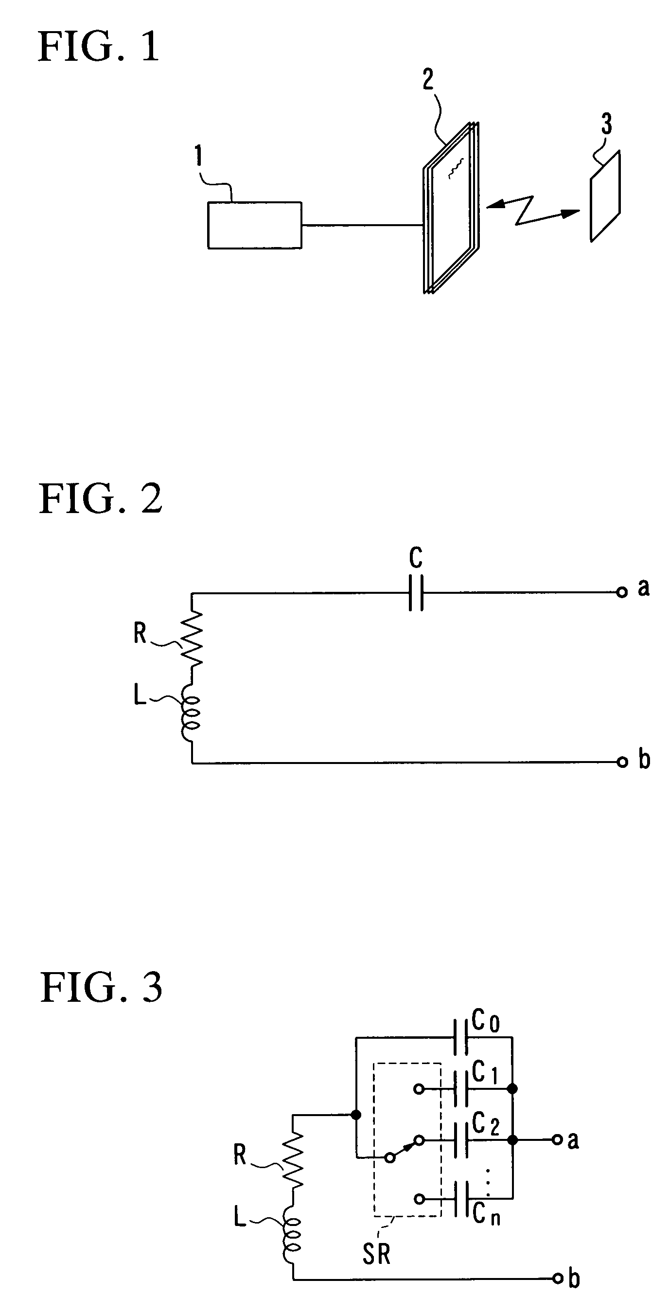
[0053]FIG. 3 is a structural diagram of the first embodiment of the invention.

[0054]In this figure, the inductance component L of the antenna and the resistance component R of the antenna are the same constituting elements as those shown in FIG. 2, and capacitors C0, C1, C2, . . . , and Cn are provided in place of the capacitor C in FIG. 2. The capacitors C0, C1, C2, . . . , and Cn have one ends connected together.

[0055]The other ends of the capacitors C1, C2, . . . , and Cn are connected to respective selectable contacts of a rotary switch SR whose common contact is connected to the other end of the capacitor C0.

[0056]This structure permits the capacitor C0 to be connected in parallel to one of the capacitors C1, C2, . . . , and Cn. If the capacitors C1, C2, . . . , and Cn have different capacitances, the combined capacitance can be made variable.

[0057]Therefore, the resonance frequency of the antenna device can be kept at a predetermined value step by step by manipulating the rota...

second embodiment

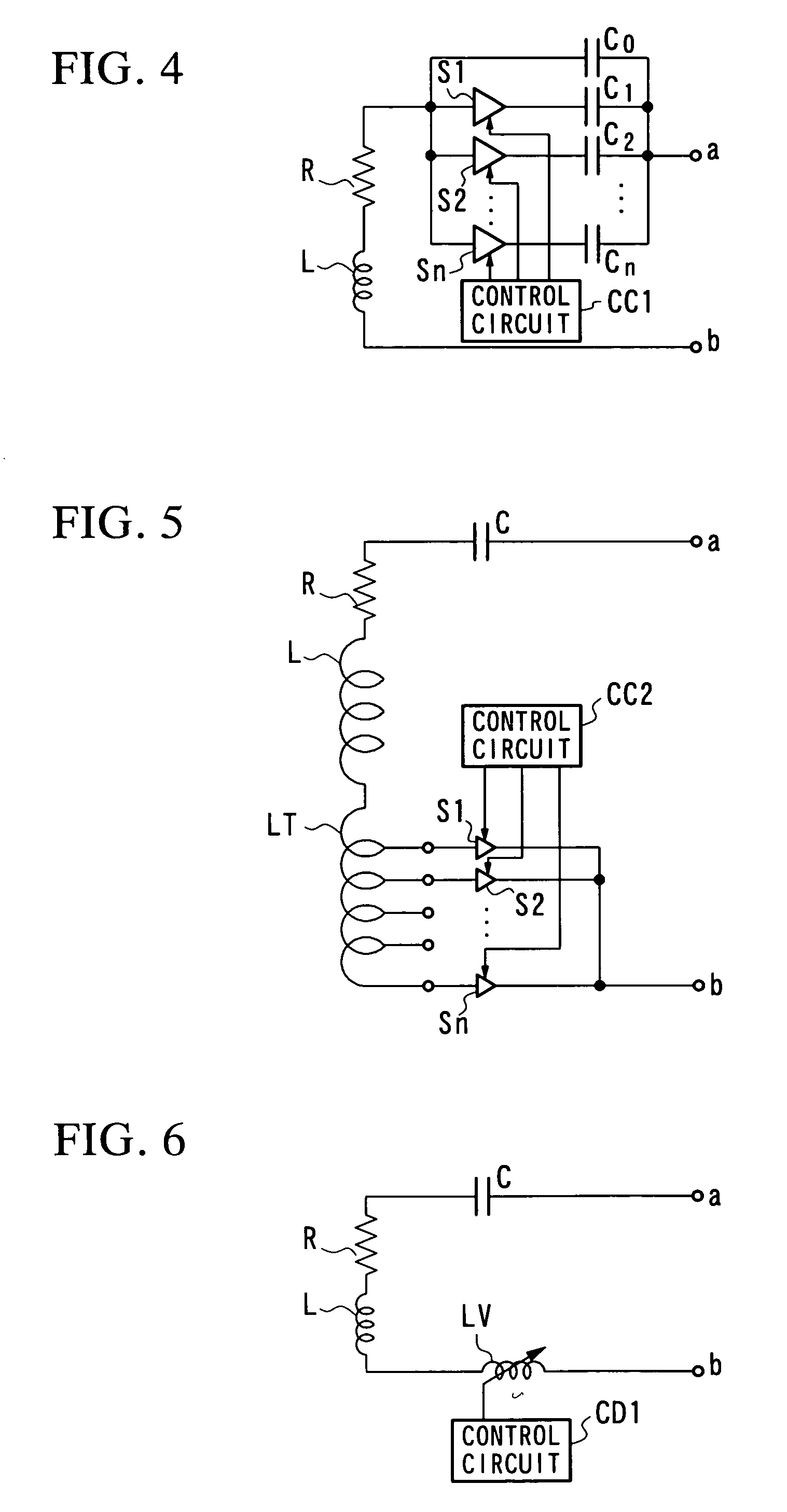
[0058]FIG. 4 shows the second embodiment of the invention.

[0059]The capacitors C0, C1, C2, . . . , and Cn in this figure respectively correspond to those capacitors with the same symbols in FIG. 3. In the second embodiment, semiconductor switches S1, S2, . . . , and Sn are provided in place of the rotary switch SR.

[0060]The opening and closing of the semiconductor switches S1, S2, . . . , and Sn are controlled by a control circuit CC1 in such a way as to maintain the resonance frequency of the antenna device at a predetermined value.

[0061]In this example, only one of the semiconductor switches S1, S2, . . . , and Sn may be turned on or plural semiconductor switches may be turned on to increase the combined capacitance.

third embodiment

[0062]FIG. 5 shows the third embodiment of the invention.

[0063]In this embodiment, the capacitor C is fixed, and the inductance of a tapped inductor LT connected in series to the LR circuit is changed by switching the taps on the inductor LT, thereby varying the inductance of the inductor L.

[0064]The opening and closing of the semiconductor switches S1, S2, . . . , and Sn are controlled by a control circuit CC2 in such a way as to maintain the resonance frequency of the antenna device at a predetermined value. It is to be noted, however, that unlike the second embodiment, the third embodiment controls the switching action so as to turn on only one of the semiconductor switches S1, S2, . . . , and Sn.

[0065]As a modification of the third embodiment, taps may be provided on the antenna coil instead of providing the tapped inductor LT so that the resonance frequency is adjusted by switching the taps from one to another.


PUM


Abstract

An antenna device of an interrogator which constitutes an automatic identification system by exchanging information with an IC tag attached to an object to be identified by electromagnetic coupling is disclosed. The antenna device comprises an antenna element, and a capacitor connected in series to the antenna element and having a variable capacitance to maintain a predetermined resonance frequency. The predetermined resonance frequency is maintained by switching taps on an antenna coil. Alternatively, the predetermined resonance frequency is maintained by switching taps on a tapped inductor or by a variable inductor.

Description

BACKGROUND OF THE INVENTION[0001]1. Field of the Invention[0002]The present invention relates to an improvement in an antenna device of an interrogator which constitutes an automatic identification system by exchanging information with an IC tag attached to an object by electromagnetic coupling. More particularly, the invention relates to a technique of maintaining a tuning frequency even when a metal body is present at the back of the antenna, thereby ensuring a communicatable distance.[0003]2. Description of the Related Art[0004]Identification systems which use bar codes as automatic identification means for identifying a target object have been widely used. As bar-code systems use inexpensive media for identification, are highly reliable, and have international standards, their use environments are being improved.[0005]These bar-code systems, however, suffer from the small amount of data which is retainable on media to be identified, and they are basically designed exclusively to...

Claims


Application Information

Patent Timeline
Patent Type & Authority Patents(United States)
IPC IPC(8): H01Q1/22H01Q7/00B42D25/305G06K7/10G06K17/00H01Q5/00H01Q5/10H04B1/59H04B5/02
CPCH01Q1/22H01Q1/2216H01Q7/005
Inventor UOZUMI, GAKUJI
Owner MITSUBISHI MATERIALS CORP
Why Eureka
Try Eureka