
Dual protocol stack for maximum speed access to a programmable logic controller (PLC) in a factor automation system

a technology of programmable logic controller and protocol stack, which is applied in the direction of electrical programme control, data switching network, instruments, etc., can solve the problems of limiting the application of the controller, the inability to differentiate traffic in terms of its purpose or the criticality of its data, and the limited control function of the controller between locations

Inactive Publication Date: 2005-11-08
SCHNEIDER AUTOMATION INC
View PDF37 Cites 67 Cited by
  • Summary
  • Abstract
  • Description
  • Claims
  • Application Information

AI Technical Summary

Problems solved by technology

This has limited application since the control system was not accessible from multiple locations.
Modems have made it possible to access the control system from different locations, but these types of systems are generally restricted to downloading and uploading data files.
Providing any type of control function between locations is rather limited in this type of environment.
The Internet network employs methods designed to handle thousands of general purpose computers sharing a single cable, and therefore has no ability to differentiate traffic in terms of its purpose or the critically of its data.
Downloading and running applets can be slow in comparison to other types of compiled languages.
These networks are usually slow, are not universally accessible and are limited to monitoring and data exchange.
Control may be implemented, but since the communication networks are non-deterministic, control is not real time.
Specialized industrial networks using proprietary fieldbus alternatives can be very expensive.
There are significant installation and other deployment costs associated with the existence of such intermediate devices.
Firewalls between the Web server and the application are designed to solve problems of security and are not designed for high performance.

Method used


Image

  • Dual protocol stack for maximum speed access to a programmable logic controller (PLC) in a factor automation system
  • Dual protocol stack for maximum speed access to a programmable logic controller (PLC) in a factor automation system
  • Dual protocol stack for maximum speed access to a programmable logic controller (PLC) in a factor automation system

Examples


Embodiment Construction

[0015]Although this invention is susceptible to embodiments of many different forms, a preferred embodiment will be described and illustrated in detail herein. The present disclosure exemplifies the principles of the invention and is not to be considered a limit to the broader aspects of the invention to the particular embodiment as described.

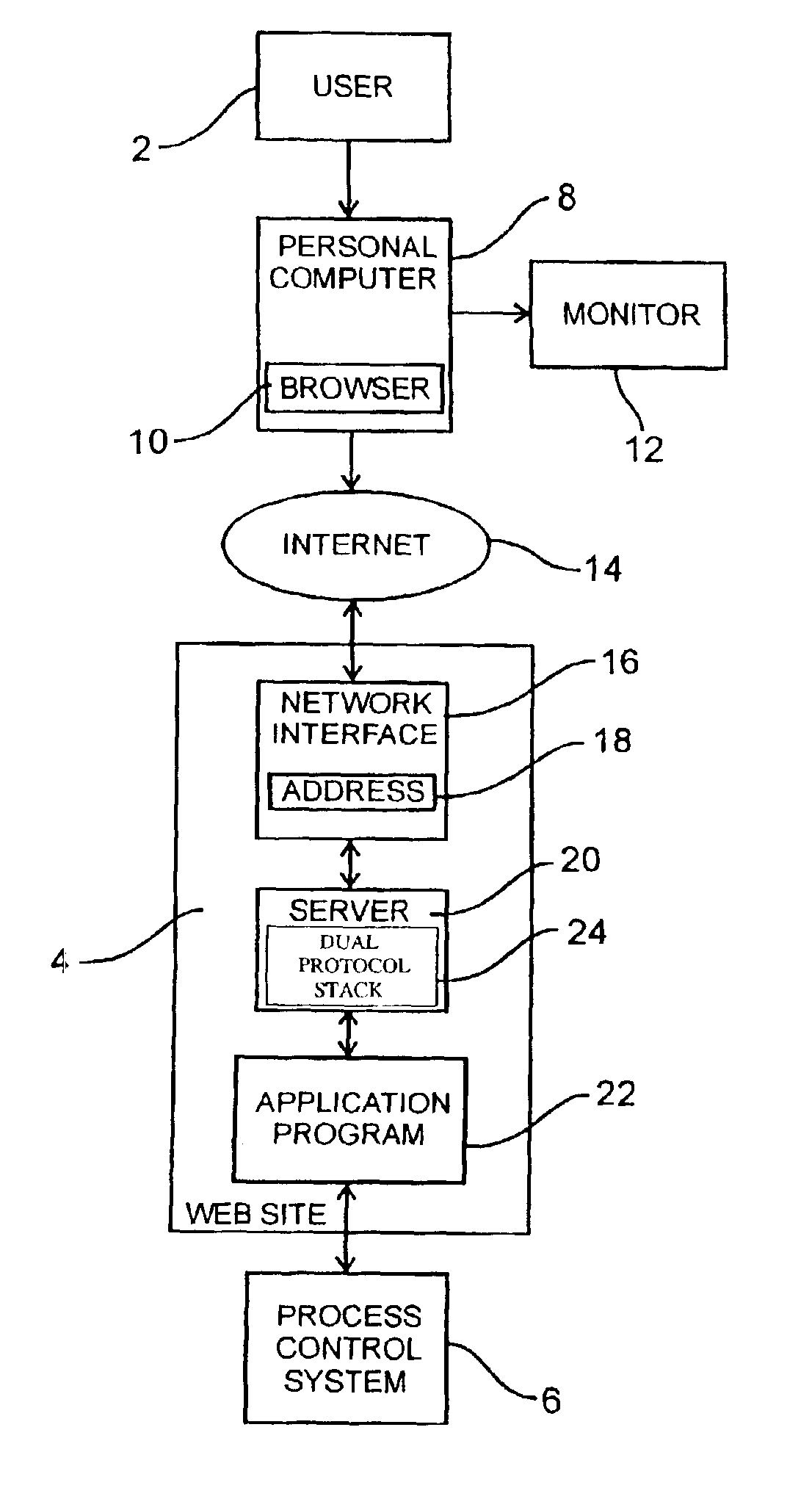
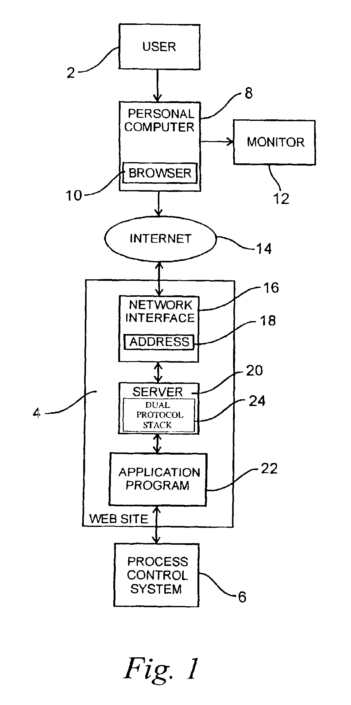
[0016]FIG. 1 shows an overview block diagram of typical system illustrating the relationship between an user 2 at a remote location and an Internet web site 4 used for monitoring a process control system 6. The user 2 will have a personal computer (PC) 8 having a commercially available browser 10, such as Netscape Communication's Navigator or Microsoft's Internet Explorer, installed for viewing the contents at the web site 4 by a monitor 12 through a network, such as the Internet 14. The PC provides a remote human-machine interface (HMI) to the process control system 6. Various interconnection services are readily available to provide the physi...


PUM


Abstract

A control system includes an Internet web interface to a network of at least one programmable logic control system running an application program for controlling output devices in response to status of input devices. The Web interface runs Web pages from an Ethernet board coupled directly to the PLC back plane and includes an HTTP protocol interpreter, a PLC back plane driver, a TCP / IP stack, and an Ethernet board kernel. The Web interface provides access to the PLC back plane by a user at a remote location through the Internet. The interface translates the industry standard Ethernet, TCP / IP and HTTP protocols used on the Internet into data recognizable to the PLC. Using this interface, the user can retrieve all pertinent data regarding the operation of the programmable logic controller system.

Description

RELATED APPLICATIONS[0001]This application is a continuation application of U.S. patent application Ser. No. 09 / 477,113, filed Dec. 31, 1999 now U.S. Pat. No. 6,587,884, which is a continuation-in-part of U.S. patent application Ser. No. 09 / 303,458, filed Apr. 30, 1999, now U.S. Pat. No. 6,151,625, which is a continuation-in-part of U.S. patent application Ser. No. 08 / 927,005, filed Sep. 10, 1997, now U.S. Pat. No. 6,282,454. This application is also related to the following commonly assigned applications entitled “Apparatus for Controlling Internetwork Communications,” U.S. patent application Ser. No. 08 / 926,837, now U.S. Pat. No. 6,321,272, and “System For A Modular Terminal Input / Output Interface For Communicating Messaging Application Layer Over Encoded Ethernet To Transport Layer,” (amended and originally entitled, “Messaging Application Layer (MODBUS) Over Ethernet To Transport Layer (TCP) Communications Method and Apparatus For a Modular Terminal Input / Output System”), U.S. p...

Claims


Application Information

Patent Timeline
IPC IPC(8): G05B19/05H04L29/06H04L29/08G06F13/00H04L12/24H04Q9/00
CPCG05B19/05G05B19/054H04L29/06H04L41/0803H04L67/025H04L69/16H04L69/169H04L67/12H04L67/02H04L67/142H04L69/161G05B2219/1208G05B2219/15038G05B2219/31104G05B2219/31124G05B2219/31156G05B2219/31186G05B2219/31422G05B2219/32126G05B2219/34038H04L67/42H04L69/08H04L69/329H04L9/40H04L67/01
Inventor PAPADOPOULOS, A. DEANTANZMAN, ALLANNAISMITH, RONALD H.
Owner SCHNEIDER AUTOMATION INC
Features
  • Generate Ideas
  • Intellectual Property
  • Life Sciences
  • Materials
  • Tech Scout
  • Unparalleled Data Quality
  • Higher Quality Content
  • 60% Fewer Hallucinations
Learn More