Flashing and weep apparatus for masonry wall window and door installations

a technology of flashing and weeping apparatus and masonry wall, which is applied in the direction of girders, snow traps, walls, etc., can solve the problems of discontinuities in walls, difficulty in maintaining unobstructed, and often arisen problems, and achieve the effect of convenient installation and implementation

Active Publication Date: 2005-11-15
TY DAS BUILDING PROD LLC
View PDF72 Cites 71 Cited by
  • Summary
  • Abstract
  • Description
  • Claims
  • Application Information

AI Technical Summary

Benefits of technology

[0014]The membrane extending beyond the mortar joint at the brick or masonry veneer is trimmed during the installation process so as not to extend beyond the outer veneer w

Problems solved by technology

Problems often arise in construction, however, in maintaining an unobstructed space between the brick and associated back-up system.
Additionally, discontinuities in the wall, such as openings for doors and windows, require attention to detail for the tradesman to properly provide for water and moisture handling.
However, in addition to mortar entering the air space during the process of brick laying, mortar extruded during the brick-laying process from the outer brick wythe also accumulates in the air space creating blockages, either falling into the air space or simply extending into and blocking the air space.
Environmental debris may also fall, or blow, into the air space.
Obstructions from these or other sources, either singly or together, may substantially block the flow of water out of portions of the air space.
Such blockage is even more problematic in the areas surroundi

Method used


Image

  • Flashing and weep apparatus for masonry wall window and door installations
  • Flashing and weep apparatus for masonry wall window and door installations
  • Flashing and weep apparatus for masonry wall window and door installations

Examples


Embodiment Construction

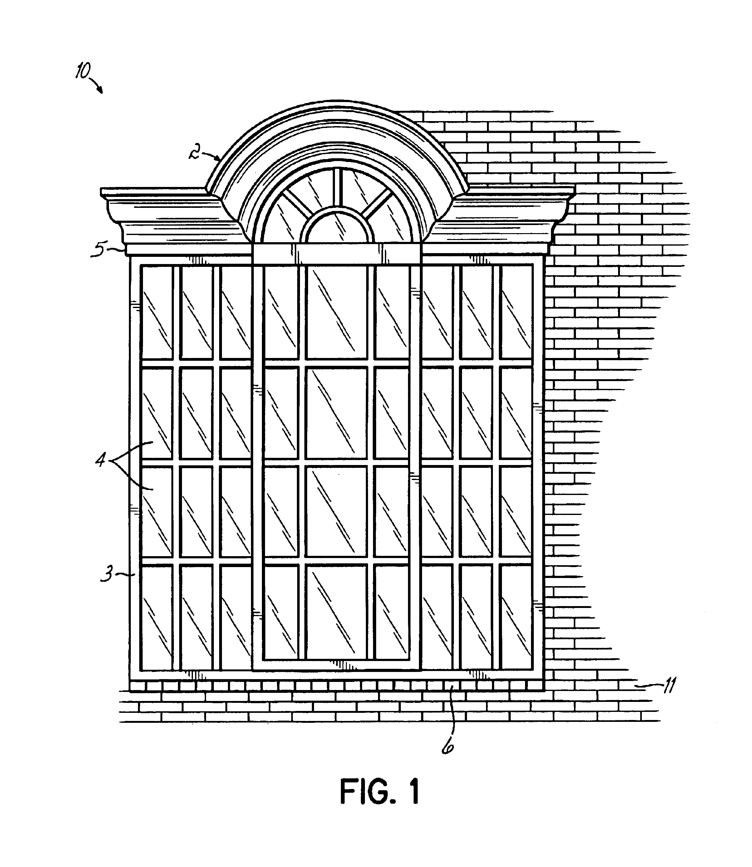
[0024]Referring to FIG. 1, an exemplary window installation 2 in a cavity wall 10 is shown. The window installation 2 includes a window frame 3, window panes 4, and a lintel 5 above and a sill 6 below the window installation 2. Although one example of a window installation is shown in FIG. 1, this invention is readily applicable for a variety of window installations, doors and other openings or interruptions in the cavity wall.

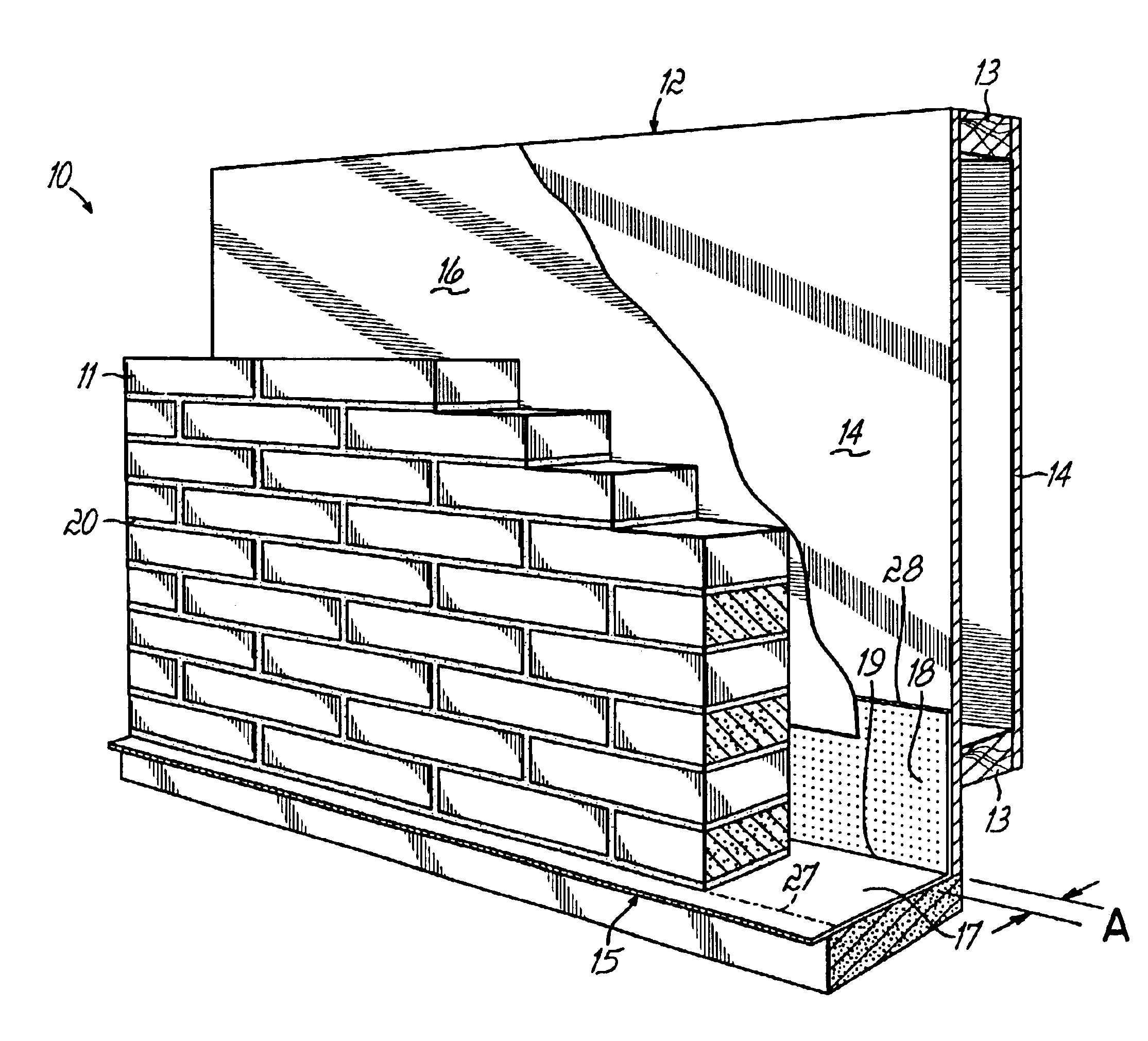
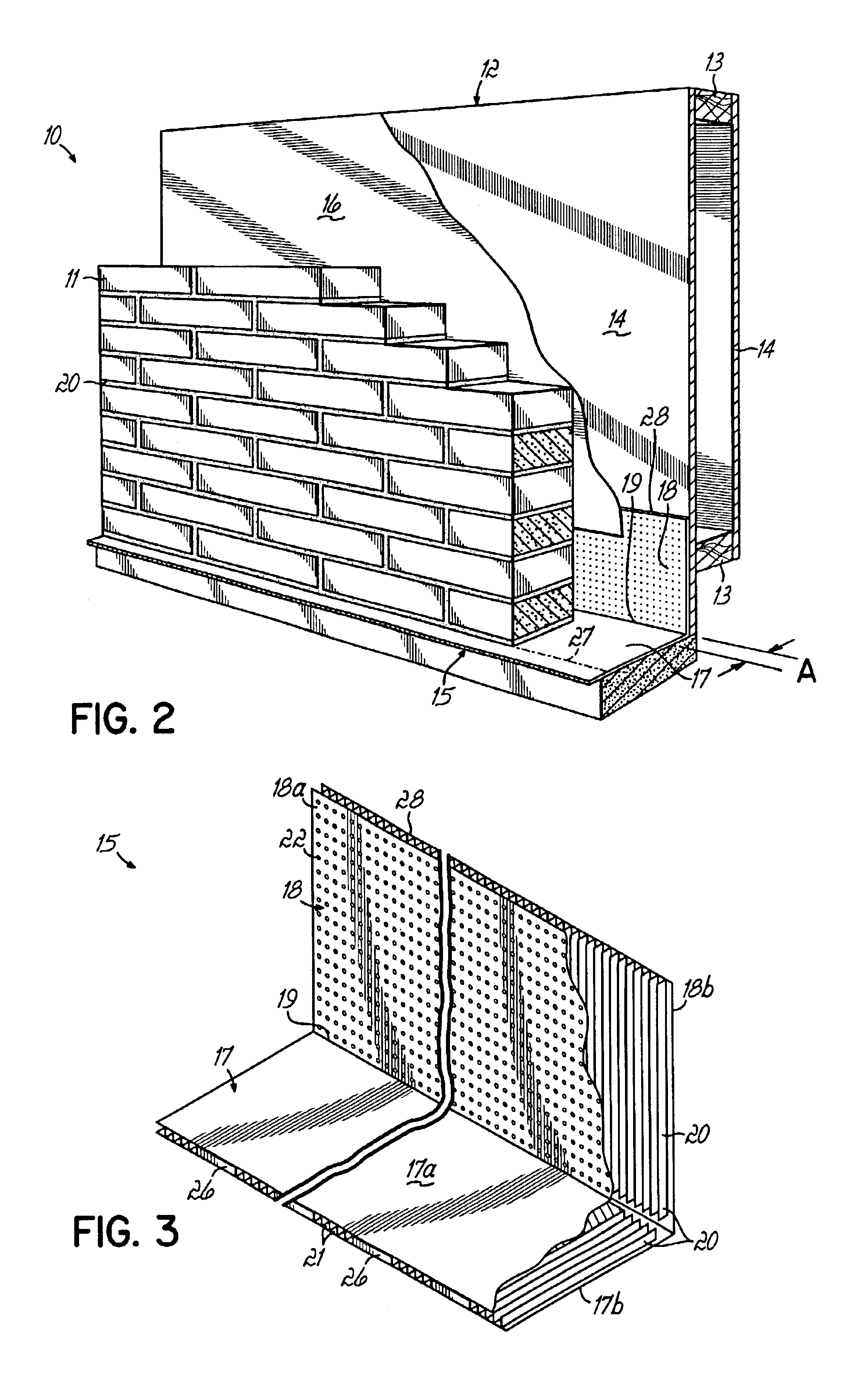
[0025]As shown more clearly in FIG. 2, the cavity wall 10 surrounding the window installation 2 in one embodiment, is comprised of a brick veneer 11 and an insulated interior wall 12. The brick veneer 11 is constructed from a plurality of bricks or blocks arranged in a pattern to construct the wall. Each brick is of a substantially rectangular shape having a uniform length, height and depth. The brick veneer 11 is built up by placing one layer of bricks over another layer, with the upper layer vertically offset from the lower layer by a distance of approximate...


PUM


Abstract

A flashing and weep apparatus allows for simple installation and accurate placement windows and doors in cavity wall construction. In a first embodiment, the flashing and weep apparatus is a two-panel extrusion that has a flashing panel that acts as a non-porous support for the masonry veneer. This embodiment also includes a second panel which is joined at a generally right angle to the first panel to be juxtaposed against the outer face of the inner wall in the cavity wall construction. Weep channels are formed between the two panels and allow for the drainage and dissipation of water and other moisture in the cavity wall system. In a second embodiment, membrane is initially attached to and draped along the lower portion of the inner wall immediately above the sill or lintel. The membrane extends across the cavity spacing between the walls to underlie the masonry components forming the outer veneer. Weep channels on the membrane communicate and transmit water and moisture from the cavity between the walls to the exterior of the veneer. The weep channels are positioned at the joint between adjacent bricks. The membrane extending beyond the mortar joint at the masonry veneer is trimmed during the installation process so as not to extend beyond the outer veneer wall while still providing an easily installed and implemented flash and weep system.

Description

[0001]This claims the benefit of U.S. Provisional Patent Application Ser. No. 60 / 389,336, filed Jun. 17, 2002 and hereby incorporated by reference in its entirety.BACKGROUND OF THE INVENTION[0002]This invention relates to brick veneer / cavity wall construction and, more particularly, to a device used in association with window and door installations in a veneer / cavity wall system to provide for proper water dissipation and moisture drainage.[0003]Walls systems having a masonry exterior are typically constructed of at least one vertical layer of masonry and at least a second vertical layer of a material forming a back-up system. The back-up system may be constructed of lumber or of a concrete masonry unit. The brick and back-up system are typically bonded together by horizontal metallic ties spaced in a vertical plane. A space is often provided in such wall systems (e.g., cavity wall systems) between the brick and back-up system for moisture drainage. Insulation may also be placed in ...

Claims


Application Information

Patent Timeline
IPC IPC(8): E04B1/70E04F19/02E06B1/00E04F13/08
CPCE04B1/70E04F13/08E04F19/02E06B1/003
Inventor COLLINS, P. MICHAELSCHAEFER, STEVEN E.
Owner TY DAS BUILDING PROD LLC
Why Eureka
Try Eureka