Return to neutral device for a hydraulic apparatus

a technology of neutral device and hydraulic apparatus, which is applied in the direction of fluid couplings, couplings, machines/engines, etc., can solve the problem of preventing the mounting of preload springs along the required line of action, and achieve the effect of compact design

Inactive Publication Date: 2005-11-15
HYDRO GEAR PARTNERSHIP
View PDF24 Cites 23 Cited by
  • Summary
  • Abstract
  • Description
  • Claims
  • Application Information

AI Technical Summary

Benefits of technology

[0010]The present invention not only returns the unit to a set position, but also helps to maintain the unit in this position. Specifically, a stroking force applied to the swash plate through a control arm or similar mechanism causes rotation of the swash plate and the swash plate, in turn, presses on one side of the return plate. The return plate then transmits a restoring force from the spring mechanism to the swash plate, through one contact point. When the stroking force is removed and the swash plate is rotated back to the set position, both contact points are engaged against the swash plate. The force balance between the two contact points keeps the swash plate at the desired set position. The force balance eliminates the dead band found in other return to neutral devices. An optional adjustment feature can be incorporated at the return plate hinge or the swash plate contact points, and can be accessed from outside the housing by means of an external screw. This adjustability eliminates many of the problems heretofore seen with other designs, as the present unit may be adjusted to compensate for design tolerances, wear or contamination, any one of which may otherwise make the actual set position differ from the desired set position.
[0011]A second embodiment has the return plate being fitted around the pump cylinder block to provide a more compact design. With such an arrangement, however, the cylinder block prevents mounting the preload spring along the required line of action relative to the return plate. In this embodiment, a second plate, referred to as a preload plate, is used to transmit force from an offset mounted spring to the return plate through two contact points. The correct spring force line of action on the return plate is obtained by the geometry of the preload plate contact points and the spherical pivot of the preload plate. This embodiment enables the use of a more compact design where such may be appropriate.

Problems solved by technology

With such an arrangement, however, the cylinder block prevents mounting the preload spring along the required line of action relative to the return plate.

Method used


Image

  • Return to neutral device for a hydraulic apparatus
  • Return to neutral device for a hydraulic apparatus
  • Return to neutral device for a hydraulic apparatus

Examples


Embodiment Construction

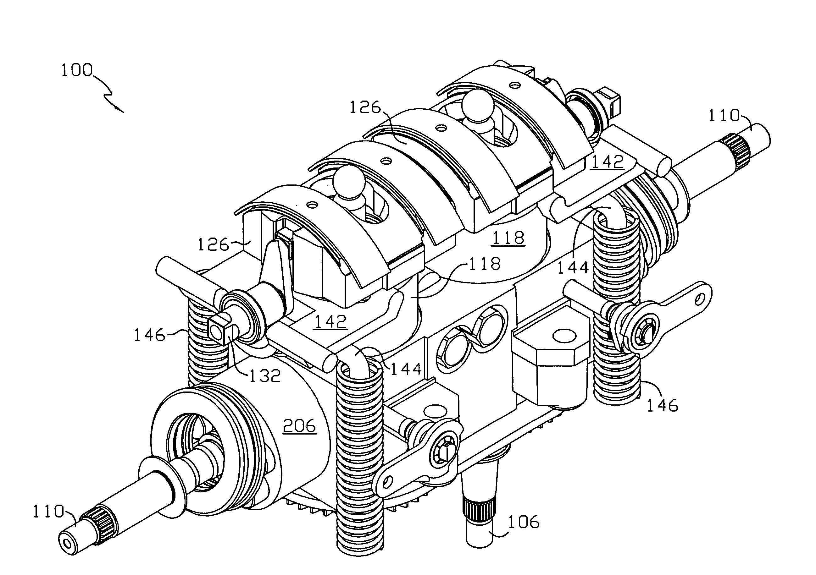
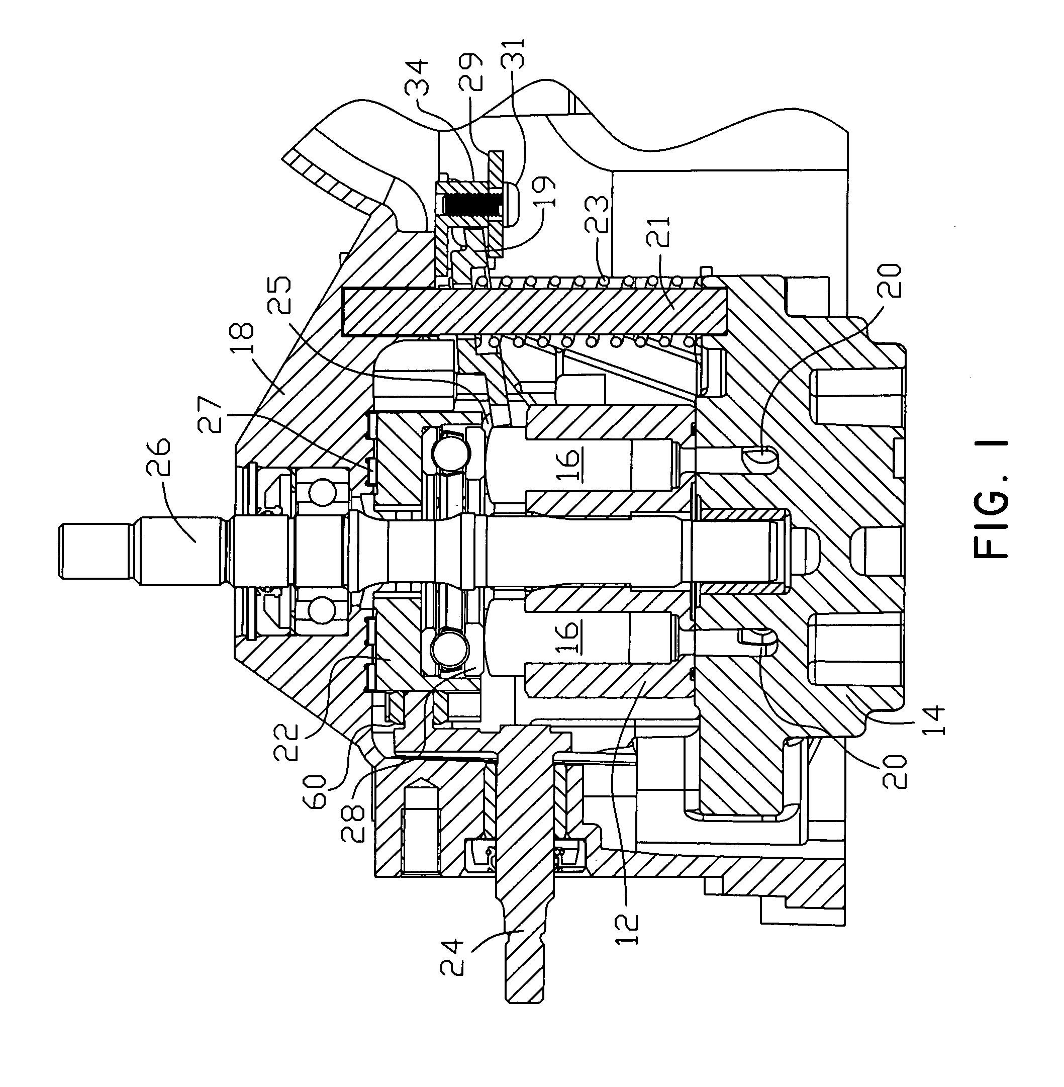
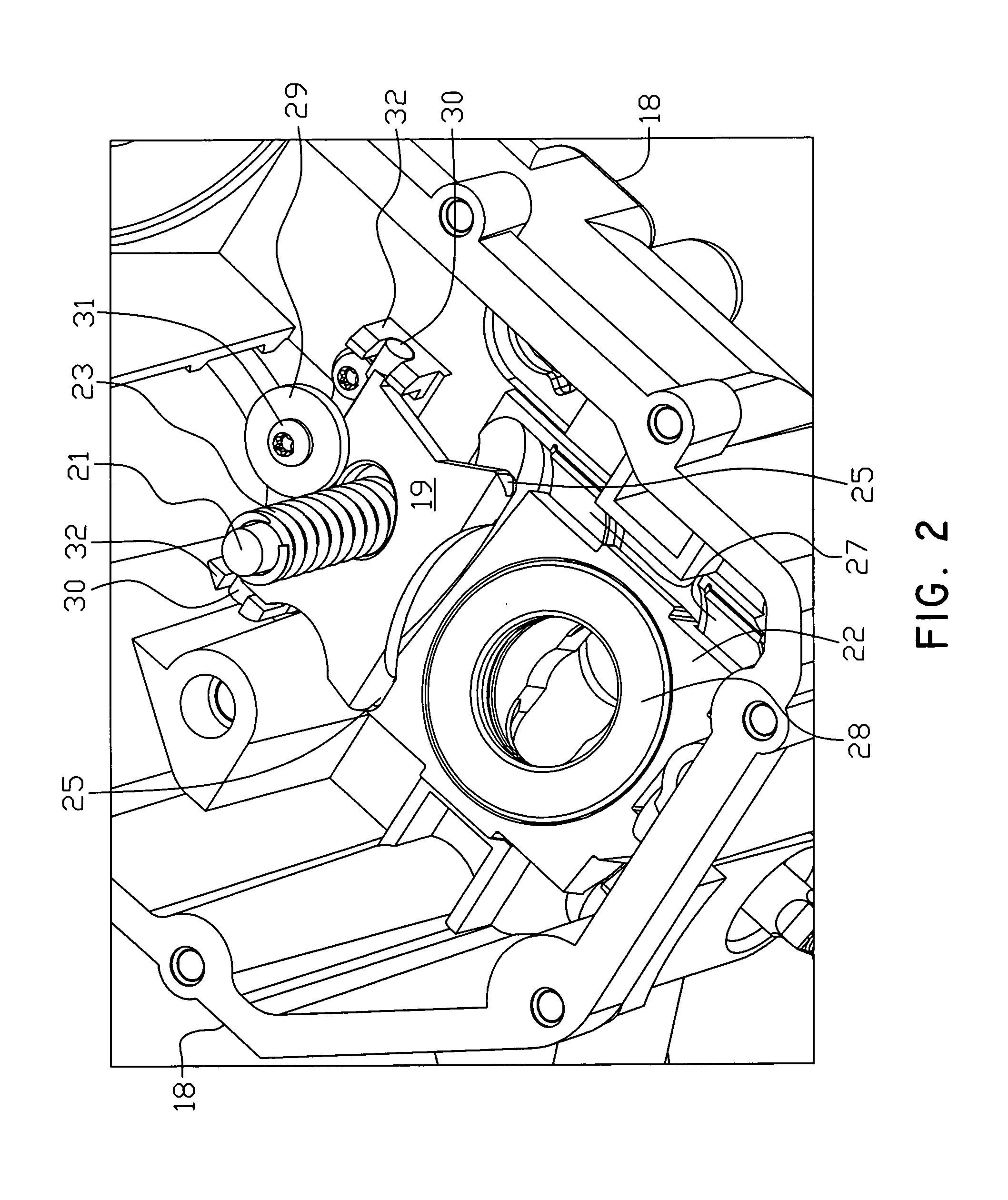
[0036]FIG. 1 shows a cross-sectional view of a standard hydraulic pump as may be used in a hydrostatic application. FIGS. 4 and 5 show certain components of a typical hydrostatic application incorporating the present invention, namely a hydrostatic pump rotatably mounted on a center section. The operation of a hydrostatic application such as a pump, HST or IHT are generally known in the art and will not be described in detail herein. For example, the arrangement of pump 12, center section 14 and the hydrostatic motor are generally described in U.S. Pat. No. 5,314,387, the terms of which are incorporated herein by reference. As noted, this invention could be used in a device having only a pump 12 without the separate hydraulic motor, or with the motor in a separate housing.

[0037]Pump cylinder block 12 is rotatably mounted on center section 14, which includes a plurality of hydraulic porting 20 to transfer hydraulic fluid to another component, such as external hoses (not shown) or a h...


PUM


Abstract

In a hydrostatic device using an axial piston pump, a return plate is mounted so that it contacts the movable swash plate of the hydrostatic transmission. The plate is biased by a spring-type mechanism to force the swash plate to return to neutral, and the set position of the plate may be externally adjusted. A bias arm comprising a generally U-shaped member having spring mounted on either leg thereof may be engaged to the return plate.

Description

CROSS-REFERENCE TO RELATED APPLICATION[0001]This application is a continuation-in-part and claims the benefit of U.S. patent application Ser. No. 10 / 144,280 filed on May 10, 2002, now U.S. Pat. No. 6,701,825, which claims the benefit of U.S. Provisional Patent Application Ser. No. 60 / 290,838 filed May 14, 2001. This application also claims the benefit of U.S. Provisional Application Ser. No. 60 / 439,765 filed Jan. 13, 2003. These applications are incorporated herein by reference in their entirety.BACKGROUND[0002]This invention relates to an improved design of a variable displacement hydraulic unit such as a pump or hydrostatic transmission (“HST”), and in particular to an improved return to neutral feature. Hydrostatic transmissions and other hydraulic units using an axial piston design are well known in the art. While this invention will be generally described in connection with an HST, it is understood that this invention could be applied to a variety of hydrostatic units, such as ...

Claims


Application Information

Patent Timeline
Patent Type & Authority Patents(United States)
IPC IPC(8): F16D31/02
CPCF16D31/02
Inventor LANGENFELD, THOMAS J.
Owner HYDRO GEAR PARTNERSHIP
Why Eureka
Try Eureka