Conveyor chain guide system

a chain guide and conveyor technology, applied in conveyor parts, rollers, transportation and packaging, etc., can solve the problems of chain guide style, chain guide tight or loose sections, excessive wear, etc., and achieve the effect of less plastic material, cost saving, and convenient cleaning

Inactive Publication Date: 2005-11-15
SOLUS INDAL INNOVATIONS
View PDF19 Cites 15 Cited by
  • Summary
  • Abstract
  • Description
  • Claims
  • Application Information

AI Technical Summary

Benefits of technology

[0022]Thus, the chain guide assemblies and chain guide system provide more consistent spacing between opposed guide rails in an open, easy to clean arrangement. The chain guide assemblies use less plastic material, thereby offering cost savings compared to the one-piece chain guides of the prior art. The chain guide assemblies also offer increased durability of the attachment to the plastic guide rails as compared to threaded fasteners. These and other objects and advantages will become more fully apparent from the following description taken in conjunction with the accompanying drawings.

Problems solved by technology

However, several difficulties arise in the practice of this chain guide style.
It will be understood that variations in uniform spacing between opposed guides or unevenness in the curvature can lead to tight or loose sections in the chain guide.
Tight sections cause excessive wear at that location and can even lead to the chain binding.
Loose sections also lead to excess wear as well as increased noise and vibration.
The primary difficulties in achieving uniformly spaced, smoothly curved circle segments arise from the construction of the metal framework and the attachment of the guides thereto.
Firstly, it is very difficult in practice to accurately form accurate circle segments of the size required for typical conveyor systems.
A second difficulty in configurations where the guides are attached from the side is that the fasteners used to attach the guides to the framework typically have a planar attachment surface whereas the plastic guide has a curved surface.
This leads to a lack of smooth curvature along the curved section of guide.
A third difficulty arises from the typical attachment of plastic to metal with threaded fasteners.
While plastic has advantageous properties of strength, lubricity, and ability to be readily formed into curves, it is not well suited to be secured with metal fasteners.
It should be noted that conveyor systems are typically run almost continuously at high speeds and with significant weight and vibration loads.
This physical stress tends to cause the plastic to cold swage and loosen from the fasteners.
However, there remain several drawbacks to the one-piece chain guides.
Firstly, the one-piece guides are relatively expensive to manufacture.
Opposing sides of the strips tend to wear unevenly, particularly in curved sections and replacing entire sections rather than a single side results in increased maintenance costs for conveyor systems based on one-piece chain guides.
A further drawback to the one-piece chain guides is that with a chain installed thereon, an essentially closed space is formed.
This closed space readily accumulates debris and makes cleaning the conveyor system extremely difficult.
The closed chain guide also inhibits access to the chain itself greatly reducing the convenience and serviceability of such a system.
Finally, the previously mentioned difficulties with attaching a plastic assembly to a metal framework still apply to the one-piece chain guide.

Method used


Image

  • Conveyor chain guide system
  • Conveyor chain guide system
  • Conveyor chain guide system

Examples


Embodiment Construction

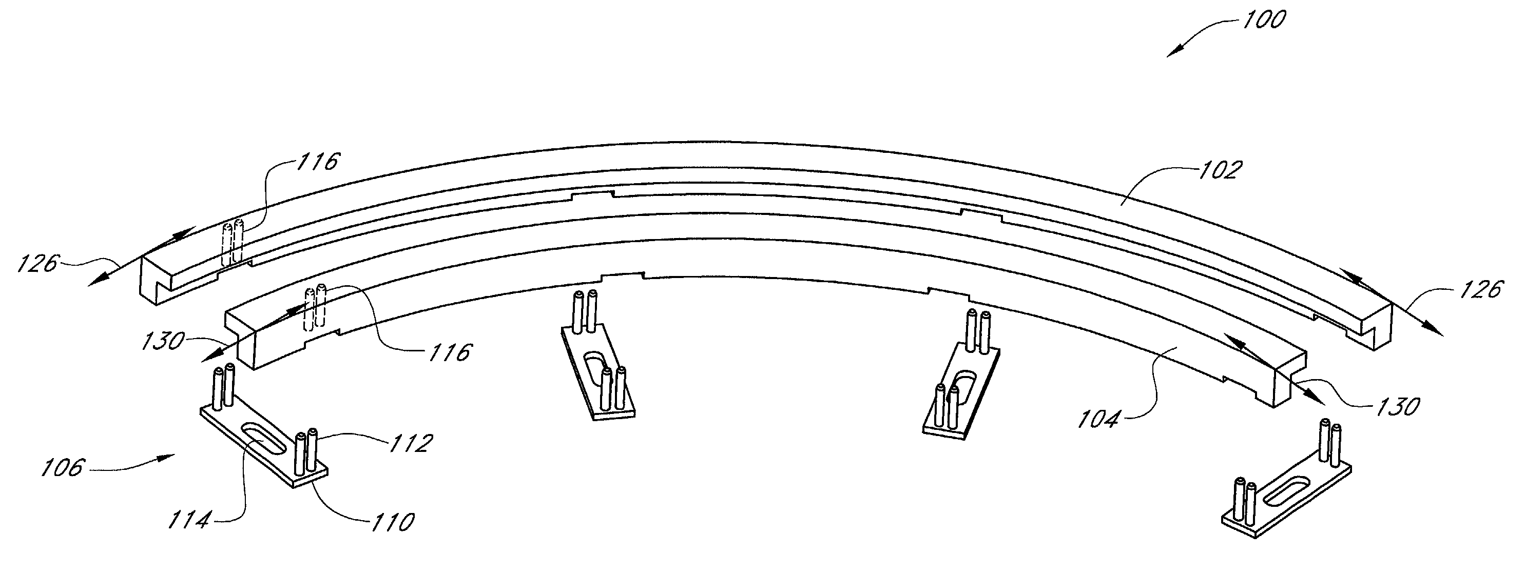
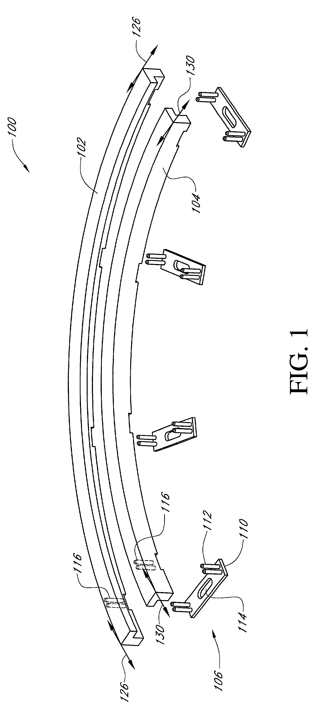
[0029]Reference will now be made to the drawings wherein like numerals refer to like parts throughout. FIG. 1 illustrates one embodiment of a curved chain guide assembly 100 in an exploded perspective view. The curved chain guide assembly 100 is adapted to locate and support a conveyor chain in a conveyor system. The conveyor chain can comprise a plurality of interconnected chain links or a continuous belt. The curved chain guide assembly 100 can be used in combination with straight chain guide assemblies 120 (FIG. 3) to enable construction of a conveyor chain guide system 140 (FIG. 5).

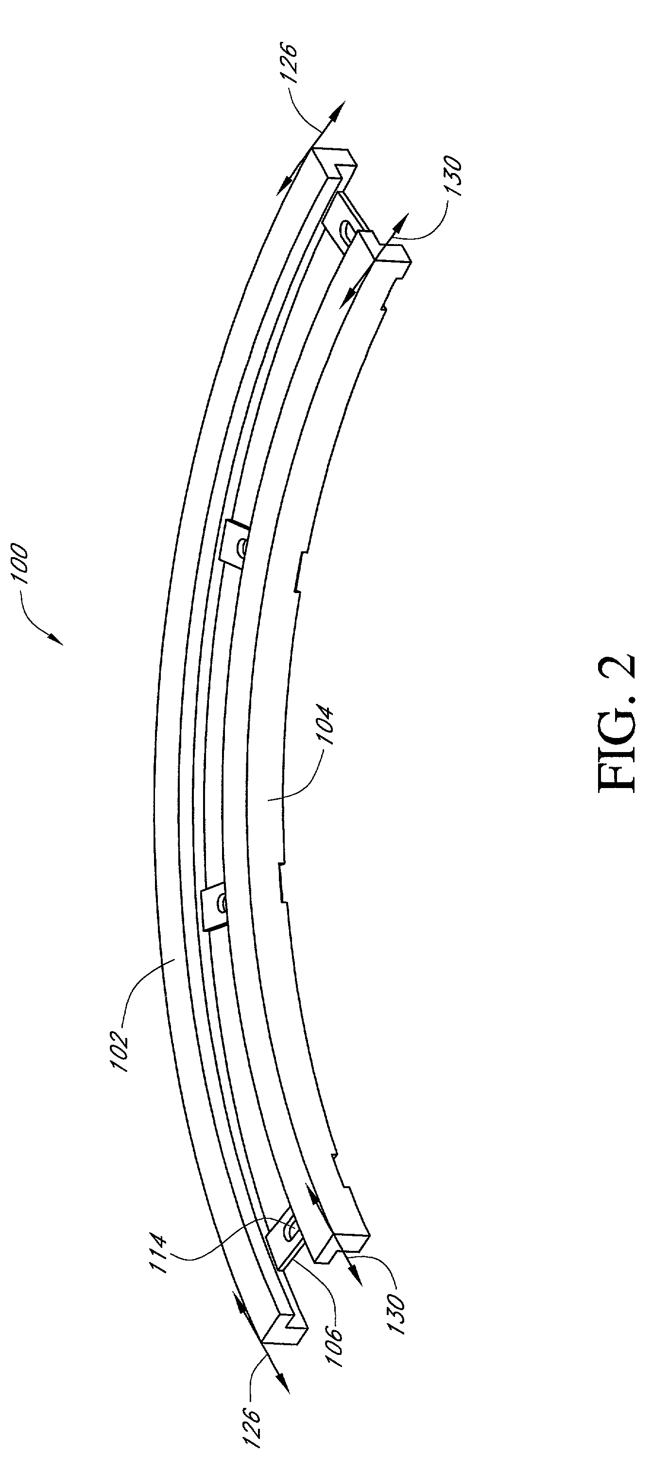
[0030]The curved 100 and straight 120 chain guide sections are adapted to be interconnected so as to abut adjacent chain guide sections 100, 120 so as to maintain the chain guide sections 100, 120 tangentially continuous at points of abutment. Thus, the chain guide sections 100, 120 facilitate construction of the conveyor chain guide system 140 with smooth transitions between adjoining curved and stra...


PUM


Abstract

Chain guide assemblies for conveyor systems including matched chain guide strips and preassembled straps that interconnect and locate the chain guide strips in constant perpendicular spacing. In certain aspects, the matched chain guide strips are preassembled with the straps to form preassembled chain guide assemblies. The chain guide assemblies can describe straight segments as well as circle segments. The chain guide assemblies present a relatively open configuration to facilitate cleaning and servicing the chain guide assemblies and attached conveyor chains.

Description

BACKGROUND OF THE INVENTION[0001]1. Field of the Invention[0002]This invention relates to the field of conveyor systems and, in particular, to an improved chain guide that offers improved durability and uniformity of positioning of chain guide strips.[0003]2. Description of the Related Art[0004]Conveyor systems are commonly employed in manufacturing applications to transport objects between different processing stations and locations. A conveyor system typically includes a conveyor chain that is arranged in an endless loop and driven about a vertically arranged plane to transport the objects on the chain surface along a generally horizontal, piecewise linear path. Guide rail assemblies are typically placed adjacent and generally parallel with the conveyor chain to retain the objects on the chain surface.[0005]Metal conveyor chains were developed more than 30 years ago and plastic versions followed shortly thereafter. Typical chains include paired tabs or bevels extending inward or o...

Claims


Application Information

Patent Timeline
Patent Type & Authority Patents(United States)
IPC IPC(8): B65G21/00B65G21/06B65G21/20
CPCB65G21/06B65G21/16
Inventor LEDINGHAM, STUART J.
Owner SOLUS INDAL INNOVATIONS
Why Eureka
Try Eureka