
Exterior fire suppression system and method for installation

a fire suppression system and fire suppression technology, applied in the field of fire suppression systems, can solve the problems of limited resources available to local firefighters, often left unprotected, and structures that are sometimes faced with fire threats

Inactive Publication Date: 2005-11-15
CROWLEY JOSEPH T
View PDF49 Cites 35 Cited by
  • Summary
  • Abstract
  • Description
  • Claims
  • Application Information

AI Technical Summary

Benefits of technology

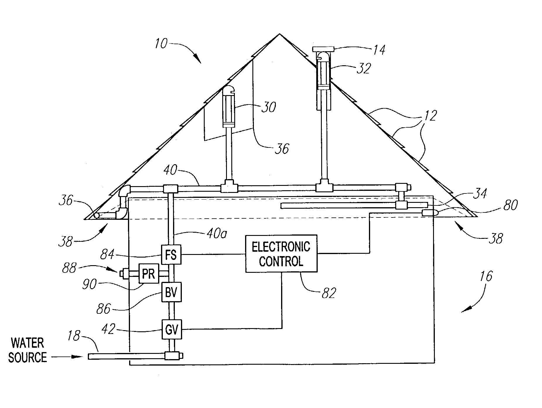
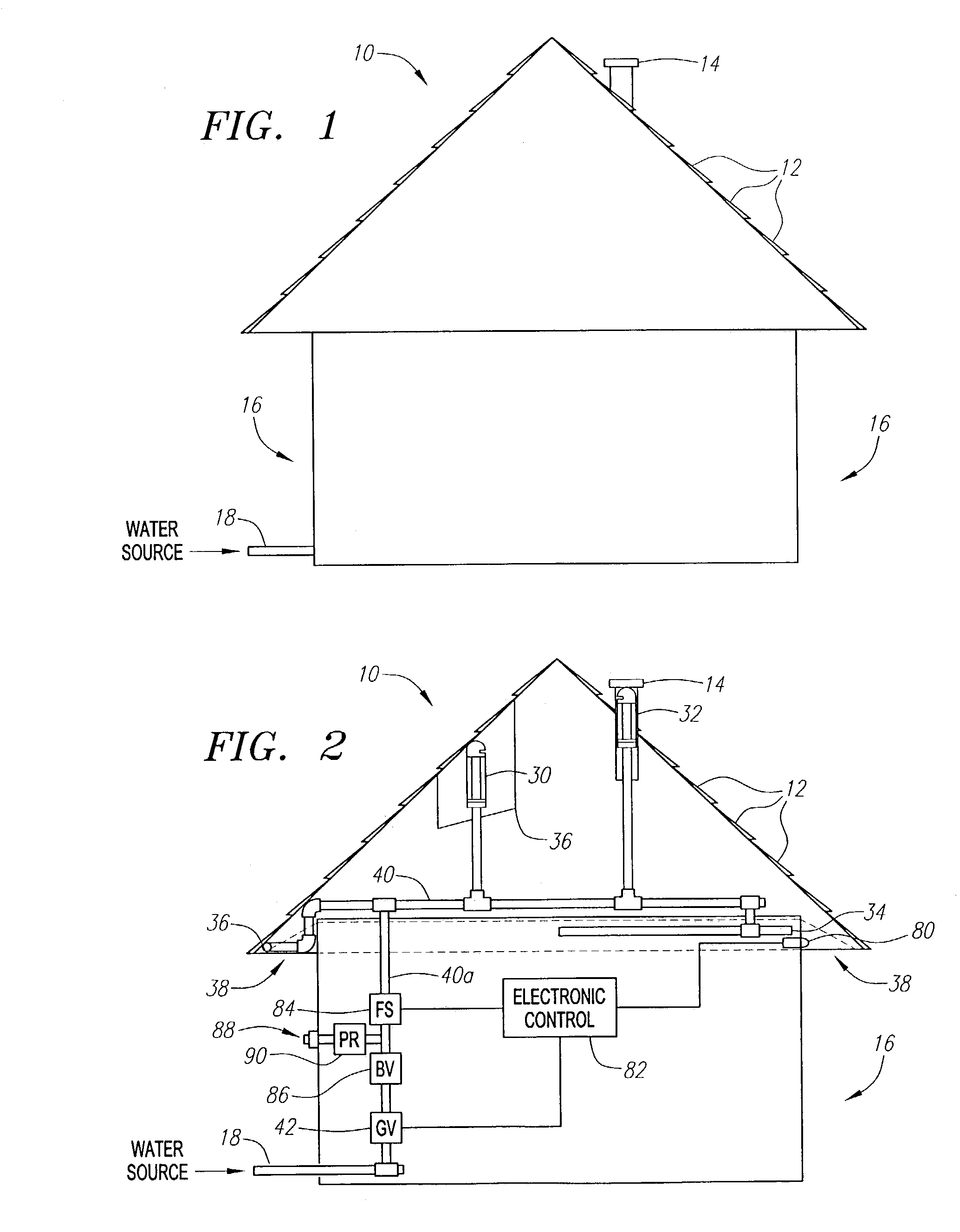
[0011]The present invention is an exterior fire suppression system, and method for installation thereof, that overcomes many of the drawbacks found in the prior art systems. In a preferred embodiment, an exterior fire suppression system includes at least one sprinkler that is connected to a water supply of a structure or a secondary water source. The sprinkler is mounted within the structure and is substantially hidden from view when the system is inactive. When activated, the sprinkler saturates a portion of the structure's exterior, providing the structure with protection from external fire threats.

Problems solved by technology

Structures, such as houses and office buildings, are sometimes faced with the threat of fire.
Structures are often left unprotected, however, from exterior fire threats such as radiant heat generated from a fire in a neighboring structure or burning embers that are blown onto the structure from a nearby fire.
When a residential neighborhood is faced with an impending fire, the resources available to local firefighters are limited, and homeowners often take additional measures to protect their houses and yards.
This approach is usually inadequate to protect the house and dangerous to the homeowner.
The windy conditions that often accompany a wildfire are likely to carry much of the water from a lawn sprinkler away from both the house and yard.
While operating the garden hose, the homeowner will often face an impending fire, thick smoke and high winds, which could result in the homeowner being seriously injured or killed from the heat, smoke inhalation or a fall from the roof.
The use of a lawn sprinkler and garden hose requires constant operation and places the homeowner in greater danger.
Another impediment to the homeowner's use of a garden hose or lawn sprinkler is the reduced availability of water during emergency situations.
Prior attempts to create an exterior fire suppression system have proven to be impractical.
These and other prior art approaches suffer from many drawbacks that have prevented the widespread implementation of exterior fire suppression systems.
For example, these systems are not aesthetically pleasing and once installed would be considered an eyesore in many communities.
The pipes are exposed to the environment, which can lead to corrosion making the system not only unsightly, but also unreliable.
Many of the prior art systems also waste water by directing water up into the wind and do not account for the reduced water pressure that is available during a fire emergency.

Method used


Image

  • Exterior fire suppression system and method for installation
  • Exterior fire suppression system and method for installation
  • Exterior fire suppression system and method for installation

Examples


first embodiment

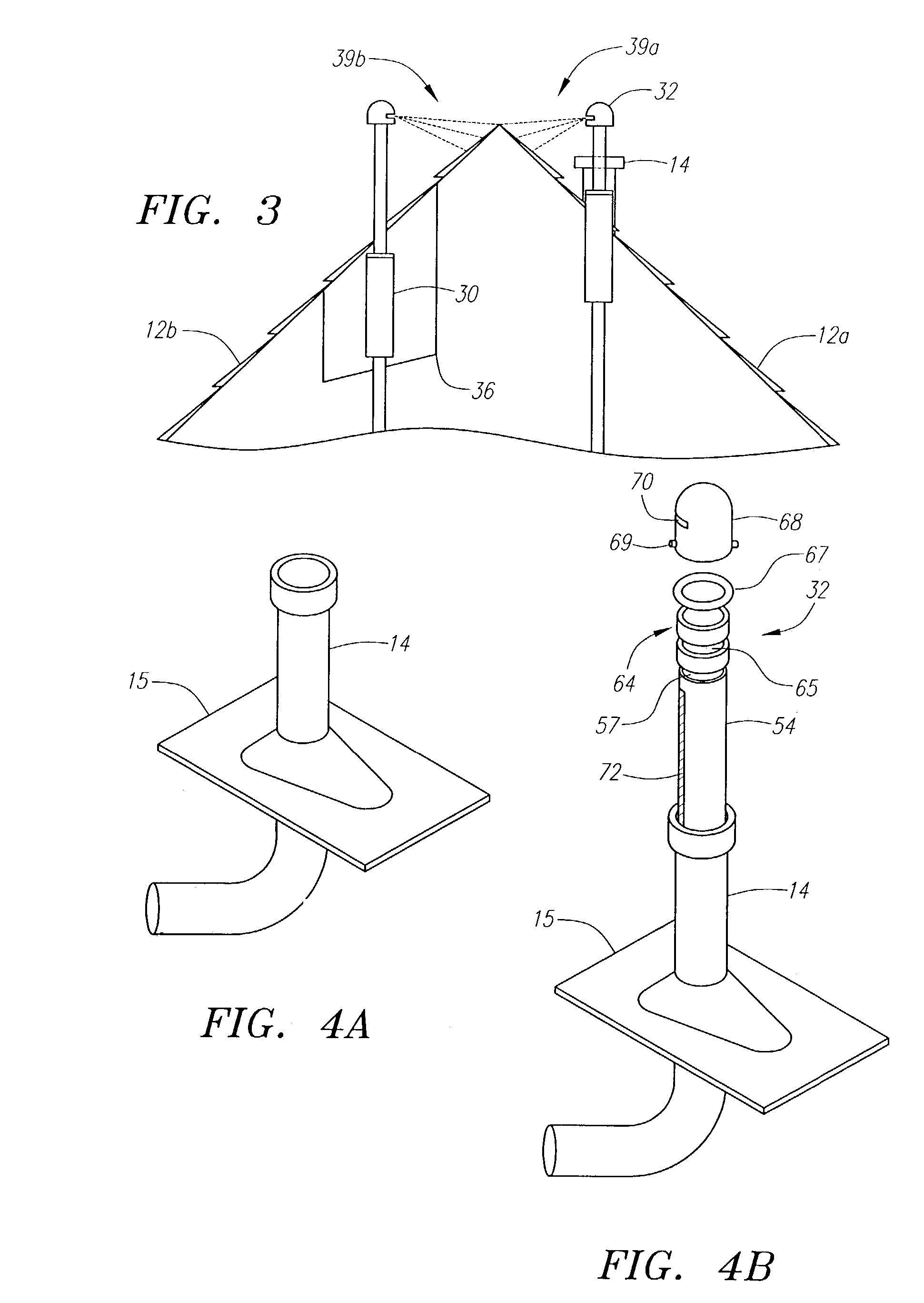
[0037]Referring to FIG. 3, each roof sprinkler 30 and 32 is adapted to saturate a portion of the roof 12a and 12b, respectively, when the system is activated. Each roof sprinkler 30 and 32 is installed within a facade that is an aesthetic match with the roof 12 or elements typically found on a roof of a similar structure. In a first embodiment, the roof sprinkler 32 is a popup sprinkler disguised as a standard plumbing roof vent 14. As illustrated in FIG. 3 and FIGS. 4a and 4b, the roof sprinkler 32 extends beyond the top of the vent facade 14 when activated to spray water 39a onto a portion of the roof 12a. The vent facade 14 may be part of a standard vent flashing 15 that is installed into the roof as known in the art. To prevent water from leaking into the interior of the structure through the vent flashing 15 when the sprinkler 32 is activated, the gaps between the sprinkler assembly and the interior of the vent facade are preferably sealed using a caulk.

second embodiment

[0038]In a second embodiment, the roof sprinkler 30 is a popup sprinkler installed in a sprinkler box 36 that is located underneath the roof 12. When activated, the roof sprinkler 30 extends beyond the top of the sprinkler box 36 to spray water 39b onto a portion of the roof 12b. Each roof sprinkler 30 and 32 is preferably adapted to spray water downward towards the roof 12 to reduce the amount of sprayed water that is carried away by the wind. In an alternative embodiment, the roof sprinklers may be adapted to deliver fire retardant foam or gel onto the structure.

[0039]Referring to FIGS. 4b, 5a and 5b, a preferred embodiment of a popup roof sprinkler 32 will now be described. In FIG. 5a the popup roof sprinkler 32 is illustrated in an inactive state. In FIG. 5b, the popup roof sprinkler 32 is illustrated in an activated state. The roof sprinkler 32 includes a housing 52 and a sprinkler head assembly 54. The housing 52 includes an outer pipe having a first end 56 adapted for connect...


PUM


Abstract

An exterior fire suppression system includes a sprinkler system that is connected to a water supply. The sprinkler system is mounted within the structure and is substantially hidden from view when the system is inactive. The system may include roof sprinklers and eave sprinklers that are adapted to saturate the exterior of the structure when the system is activated. Each roof sprinkler is a popup sprinkler installed within a facade that is an aesthetic match with the structure's roof and may be installed within a sprinkler box underneath the roofline. Each eave sprinkler is installed within the eave, substantially hidden from view. A heat sensor may be disposed adjacent to the eave sprinkler and connected to an electronic control to activate the system when excessive heat is detected.

Description

BACKGROUND OF THE INVENTION[0001]1. Field of the Invention[0002]The present invention relates generally to fire suppression systems and, in particular, to a fire suppression system for protecting a structure from exterior fire threats.[0003]2. Description of the Related Art[0004]Structures, such as houses and office buildings, are sometimes faced with the threat of fire. Many structures are protected from internal fires through an interior fire suppression system, such as an interior sprinkler system. Structures are often left unprotected, however, from exterior fire threats such as radiant heat generated from a fire in a neighboring structure or burning embers that are blown onto the structure from a nearby fire.[0005]When a residential neighborhood is faced with an impending fire, the resources available to local firefighters are limited, and homeowners often take additional measures to protect their houses and yards. For example, a homeowner may climb onto the roof of the house w...

Claims


Application Information

Patent Timeline
Patent Type & Authority Patents(United States)
IPC IPC(8): A62C3/00A62C35/60A62C3/02A62C37/09A62C37/08A62C35/58
CPCA62C3/0214A62C3/0292A62C35/60A62C37/09B05B15/10B05B15/74
Inventor CROWLEY, JOSEPH T.
Owner CROWLEY JOSEPH T
Learn More