Suspended glass panel railing system

a technology of suspended glass and railings, applied in the direction of construction, building types, agriculture, etc., can solve the problem that typical structural glass systems are not applicable to exterior applications, and achieve the effect of reducing the amount of components and labor

Inactive Publication Date: 2005-11-15
C R LAURENCE
View PDF16 Cites 60 Cited by
  • Summary
  • Abstract
  • Description
  • Claims
  • Application Information

AI Technical Summary

Benefits of technology

[0011]This new invention reduces the amount of components and labor associated with a typical post-supported railing. This new invention also solves...

Problems solved by technology

Without this elevated base feature, typical structural glass systems would not be a...

Method used


Image

  • Suspended glass panel railing system
  • Suspended glass panel railing system
  • Suspended glass panel railing system

Examples


Embodiment Construction

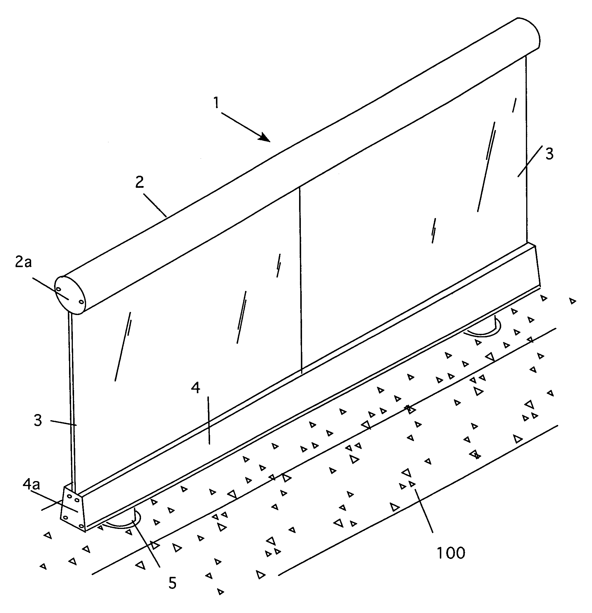
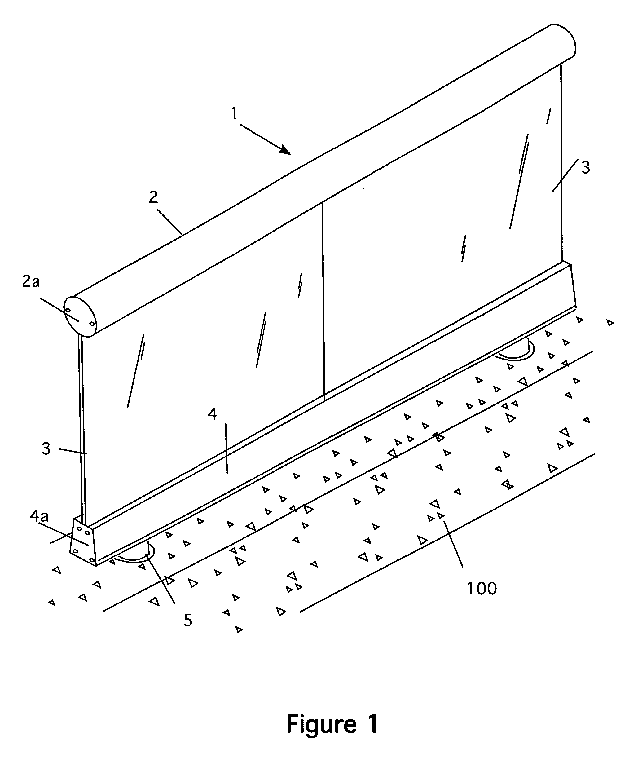
[0040]Referring now to FIG. 1, my new railing system 1 has a number of sub components. Details of these sub components follow the general description of the system. First, is a top rail 2 is used to secure the tops of glass panels 3. The glass panels are typically ½-inch thick tempered glass. The bottoms of the glass panels fit into an extruded base shoe 4. This view also shows the ends of the rail 2 and shoe 4, which are covered with end caps 2a and 4a respectively.

[0041]Unlike prior art designs, there are no full height posts. Moreover, the base shoe does not rest on the finished floor either. Instead, short support posts 5 are attached to the base shoe, as discussed below. These posts are typically grouted into a concrete slab 100 that forms the base floor of the building in which the system is used. Of course if concrete is not used, the posts are secured using techniques common to that particular art.

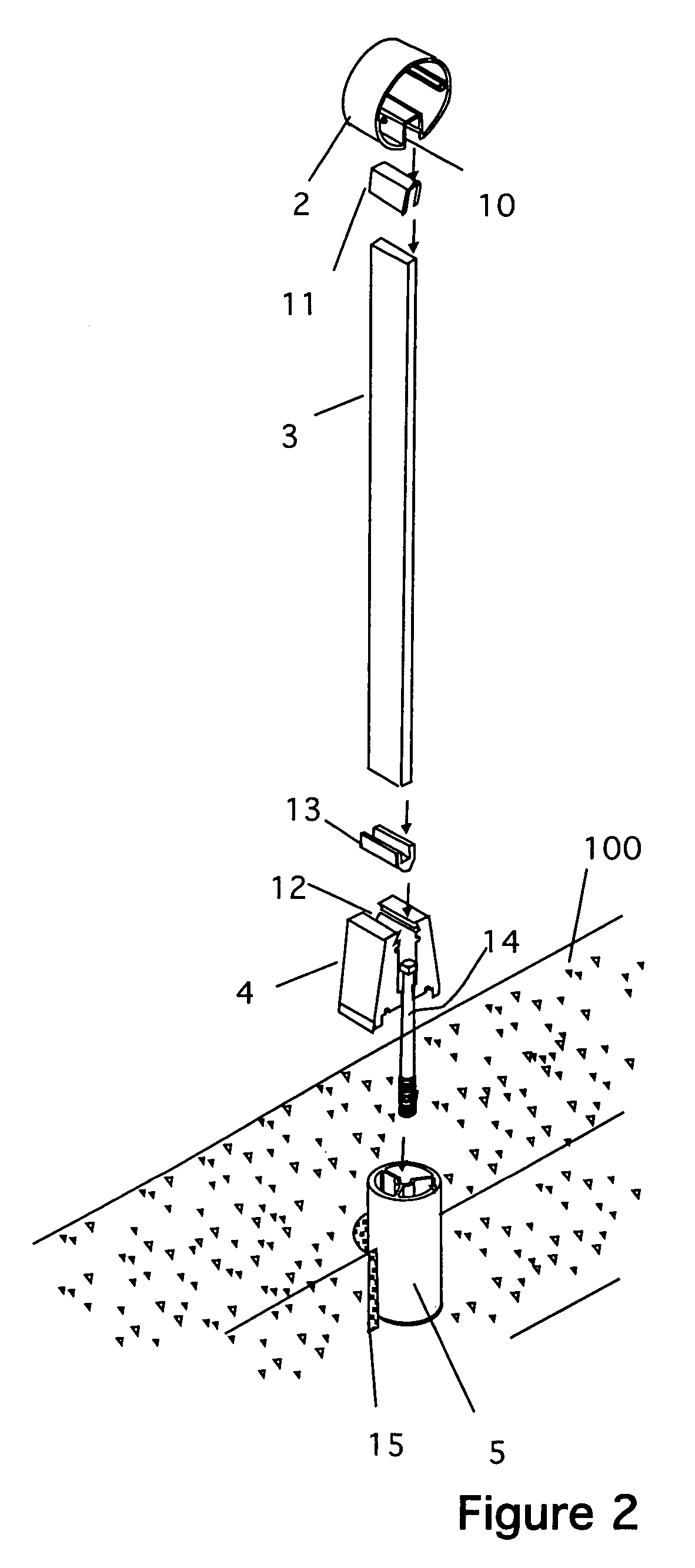
[0042]FIG. 2 shows a partially exploded view of the system. Here, the componen...


PUM


Abstract

An ornamental guardrail system that has an improved base assembly, which allows water and debris to escape from the deck surface. The system uses a mounting arrangement that supports the glass panels above the surface of the deck without using full-height posts. This mounting arrangement makes a structural glass railing useful in many types of construction projects that require the surface water to sheet flow under the railing system, or to achieve a certain visual style.

Description

CROSS REFERENCE TO RELATED APPLICATIONS[0001]Not ApplicableSTATEMENT REGARDING FEDERALLY SPONSORED RESEARCH AND DEVELOPMENT[0002]Not ApplicableBACKGROUND OF THE INVENTION[0003]1. Field of the invention[0004]This invention relates to a building construction for mounting vertical panels, and relates specifically to a structural glass guardrail system for use on interior and exterior balconies, decks, walkways, landings, and stairways.[0005]2. Description of the Prior Art[0006]Glass panel railing systems that utilize thick, glass panels as the sole vertical support are widely used as guardrails and handrails in the construction of commercial and residential building structures. These systems are typically found on elevated surfaces, acting as functional and aesthetically pleasing guardrails. Moreover, structural glass railing systems are preferred by many over other systems utilizing vertical support posts because they present much less obstruction to the visual field. Additionally, st...

Claims


Application Information

Patent Timeline
IPC IPC(8): E04H17/16E04F11/18
CPCE04F11/1812E04F11/1851E04F11/1853
Inventor HANSEN, TRACY C.
Owner C R LAURENCE
Why Eureka
Try Eureka