
Collapsible cross-arm dolly

a cross-arm and dolly technology, applied in the field of weight-moving dollies, can solve the problems of large width and breadth, and achieve the effect of convenient us

Inactive Publication Date: 2005-11-15
CHIEH PETER T C +1
View PDF12 Cites 43 Cited by
  • Summary
  • Abstract
  • Description
  • Claims
  • Application Information

AI Technical Summary

Benefits of technology

[0017]A need has existed for some time to have a cross-arm dolly that is easy to transport and store when not in use. Therefore, the primary object of the invention is to provide a cross-arm dolly that pivots in the middle and collapses into a smaller area, thus reducing the width by almost half. This functional utility does not affect the structural integrity of the dolly as the arms are basically unchanged and only a pivot junction replaces the rigid attaching hardware.
[0019]Another object of the invention is its ability to be stored on shelf or in a drawer when not in use. Normally, a cross-arm dolly is too large to store on a standard width shelf as it is too wide and protrudes beyond the limits of the shelf. The present invention precludes this problem by folding or rotating the arms until they are contiguous with one another, thus permitting easy storage since the length has not the problem and the width has been reduced to be within the size restrictions of the shelf.
[0021]Yet another object of the invention is that the dolly is easy to display in a retail establishment in its collapsed position.
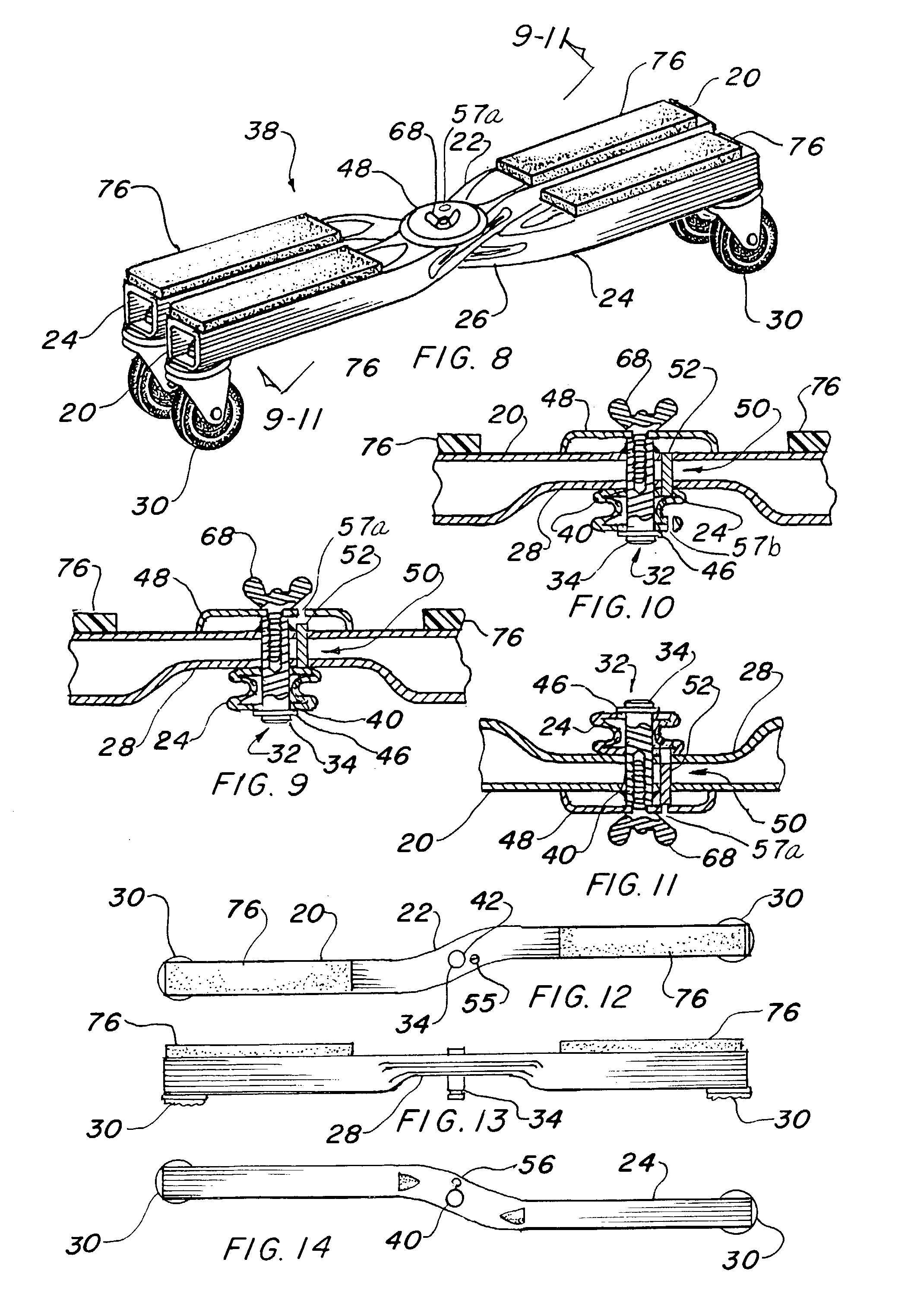
[0023]A further object of the invention is the ease of collapsing the dolly by using a securing and disengaging device to lock the arms in a cross position, which consists of a gravity actuated restraint in its preferred embodiment. When a user wants to change the arms from the cross position to the collapsed position, the dolly is simply turned upside down. Once the dolly is upside down, a cylindrical pin falls by gravity, which disengages both arms, thereby permitting manual rotation to a side by side relationship of the arms. A second embodiment is also simple and easy to employ as it only requires a user to depress a button beneath the pivot junction to disengage the cross position of the dolly. In both embodiments, the mechanism locks the arms together securely when in the cross position.

Problems solved by technology

The only drawback in this type of construction is that, while it is flat, it is also large in width and breadth, and the legs must be wide enough to balance and maintain the load.

Method used


Image

  • Collapsible cross-arm dolly
  • Collapsible cross-arm dolly
  • Collapsible cross-arm dolly

Examples


Embodiment Construction

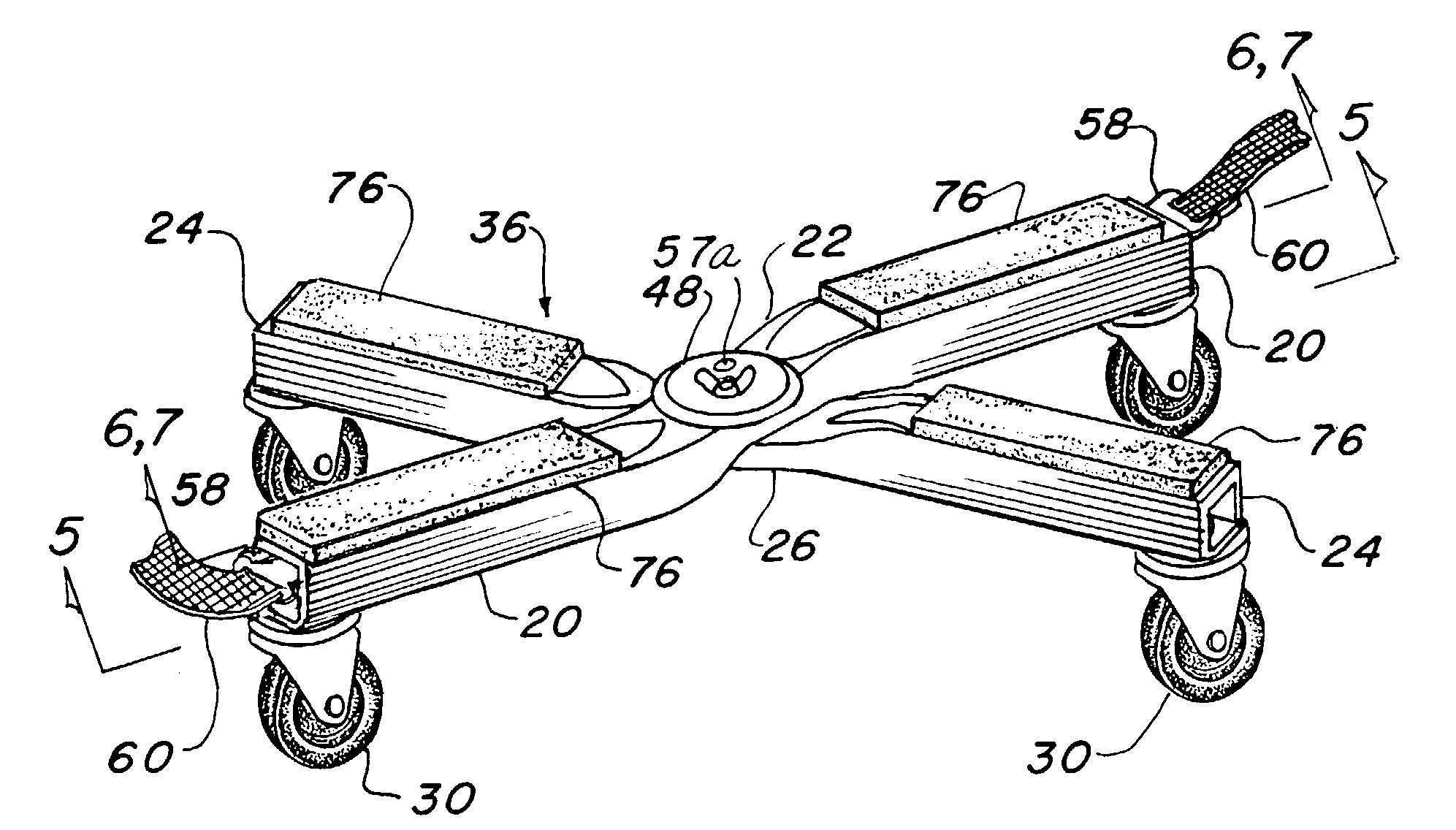
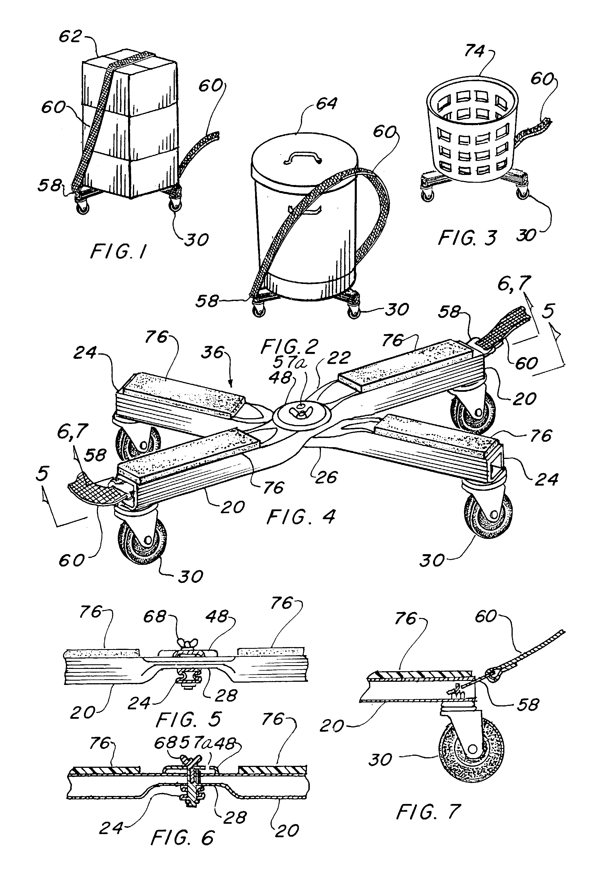
[0080]The best mode for carrying out the invention is presented in terms of a preferred and a second embodiment of a collapsible cross-arm dolly for the conveyance of weighted articles. The second embodiment only differs from the first embodiment in the method of disengaging the cross arms, thus allowing the arms to collapse in a parallel position. The preferred embodiment of the collapsible cross-arm dolly is shown in FIGS. 1 through 28 and is comprised of an upper arm 20 that includes an upper arm, horizontal offset center portion 22, and a lower arm 24 having a similar lower arm, horizontal offset center portion 26 however, it is a mirror image adaptation of the upper arm horizontal offset 22.

[0081]The upper arm 20 and lower arm 24 are both preferably formed of square metallic tubing, with the upper arm offset center portion 22 having a flattened section 28 on the arm's lower surface, or underside, as illustrated in FIGS. 5, 6, 9–11 and 13. The lower arm 24 offset center portion ...


PUM


Abstract

A collapsible cross-arm dolly for conveyance of weighted articles. The dolly consists of an upper arm (20) and a lower arm (24) of square metallic tubing, with each formed with a horizontal offset center portion (22) and (26) and with a pair of casters (30) that are attached at each end of both arm's lower surface. The horizontal offset center portion (22) is formed in opposite hand or mirror image of each other, thus permitting them to nest together and are both oppositely flattened to allow nesting on the same horizontal plane. A pivot junction (32) is mutually disposed between the arms, thereby permitting the dolly to form a pivotal right angle cross position (36), or alternatively, a pivotal parallel arm collapsed position (38). A gravity-actuated restraint (50) locks and disengages the connection of the upper arm to the lower arm, which permits changing orientation from the right angle cross position (36) to the parallel arm collapsed position (36). A second embodiment is basically identical except a manual push-button restraint (78) is utilized instead of being operated by a gravity actuated restraint.

Description

TECHNICAL FIELD[0001]The invention generally pertains to weight-moving dollies, more specifically to a four-caster, cross-arm dolly that collapses which achieves a reduction in size for convenient transportation and storage.BACKGROUND ART[0002]Previously, devices for moving relatively small cargo and personal items, such as luggage, have been limited to wheeled trucks which are usually constructed of a robust material with a toe plate extending near the bottom for stacking the cargo or luggage. Many varieties and styles of trucks, which are also known as “dollies”, have been used, such as a continuous handle type, bicycle handle, pistol grip handle, single and double loop style, and also “S” pin or tee-type handles. All of these varieties use the same principle of stacking with gravity and holding the items against the dolly's frame when angled backward toward the operator. The two wheels provide the mobility and steering is accomplished manually.[0003]For larger quantities of cargo...

Claims


Application Information

Patent Timeline
IPC IPC(8): B62B1/00B62B5/00
CPCB62B5/0083B62B2203/00B62B2205/00B62B2205/06
Inventor CHIEH, PETER T. C.BAKER, FRANKLIN W.
Owner CHIEH PETER T C
Learn More