Optical recording medium with prepit regions and recording/reproducing method thereof

a technology of optical recording medium and pre-recording region, which is applied in the direction of instrumentation, light beam reproducing, disposition/mounting of heads, etc., can solve the problems of reducing the residual error of tracking control, difficult to shorten the wavelength of reproduction light or increase the numerical aperture of an objective lens, and it is difficult to conduct laser annealing for a long time. , to achieve the effect of increasing the recording density

Inactive Publication Date: 2005-11-15
PANASONIC CORP
View PDF12 Cites 24 Cited by
  • Summary
  • Abstract
  • Description
  • Claims
  • Application Information

AI Technical Summary

Benefits of technology

[0026]In view of the above, the object of the present invention is to provide an information recording medium in which tracking control can be conducted with reliability and recording density can be increased.
[0027]In order to achieve the above-mentioned object, a first information recording medium of the present invention, for reproducing information by irradiation with a laser beam condensed by an objective lens with a numerical aperture NA, includes a disk-shaped substrate and a recording layer disposed on the substrate, wherein, on a surface of the substrate, a plurality of prepit regions and a plurality of data regions are disposed alternately along spiral or concentric virtual track centers, each prepit region includes a pair of wobble pits for tracking servo, and a length L (μm) of the wobble pit along the virtual track center, a wavelength λ (μm) of the laser beam, and the NA satisfy a relationship: 0.3≦L·NA / λ≦0.65. In the first information recording medium, irrespective of the position on the substrate, the amplitude of a reproduction signal from a wobble pit becomes constant. Therefore, the first information recording medium allows tracking control to be conducted with reliability, and high-density recording to be conducted. Furthermore, the magnitude of interference caused by wobble pits in adjacent tracks shown in FIG. 18B is proportional to the length of the wobble pits. Therefore, by shortening the wobble pits, the interference can be reduced, and the tracking accuracy can be enhanced substantially in the case where an optical disk is tilted in a radius direction. In the present specification, “one track” refers to a single revolution.
[0028]In the first information recording medium, it is preferable that flat portions are present on the surface of the substrate before and after the wobble pits along the virtual track center, and a length M (μm) of the flat portion along the virtual track center and the spot diameter D (μm) satisfy a relationship: 0.65≦(M / D). According to this configuration, even when a tangential tilt occurs, tracking control can be conducted with reliability. Therefore, for example, information can be reproduced by using the DWDD method that is likely to be influenced by a residual error of tracking control, and the linear density can be enhanced.
[0029]A second information recording medium of the present invention, for reproducing information by irradiation with a laser beam condensed by an objective lens with a numerical aperture NA, includes a disk-shaped substrate and a recording layer disposed on the substrate, wherein, on a surface of the substrate, a plurality of prepit regions and a plurality of data regions are disposed alternately along spiral or concentric virtual track centers, each prepit region includes a pair of wobble pits for tracking servo, flat portions are present on a surface of the substrate before and after the wobble pits along the virtual track center, and a length M (μm) of the flat portion along the virtual track center, a wavelength λ (μm) of the laser beam and the NA satisfy a relationship: 0.65≦M·NA / λ. In the second information recording medium, even when a tangential tilt occurs, tracking control can be conducted with reliability. Therefore, for example, information can be reproduced by using the DWDD method that is likely to be influenced by a residual error of tracking control, and a linear density can be enhanced.
[0032]In the first and second information recording media, grooves may be formed in portions corresponding to the data regions in the substrate. According to this configuration, a tracking system can be adopted in which a tracking error of push-pull tracking using grooves is corrected with wobble pits. In this case, compared with the tracking system using only wobble pits, the number of servo regions per track can be decreased. Therefore, high-density recording can be conducted. Furthermore, a recording / reproducing system can be adopted in which recording tracks are cut off magnetically as in the DWDD method. Therefore, a linear density can be enhanced.
[0035]In the first and second information recording media, a distance between each center of the pair of wobble pits and an end of the prepit region may be represented by an integral multiple of T / N, where T is a length of the prepit region along the virtual track center and N is an integer of 5 or more. Herein, the end of a prepit region refers to the end of a prepit region on the side a laser beam spot enters during reproduction. According to this configuration, it easily can be determined to which pattern a portion through which a light spot passes belongs.

Problems solved by technology

However, this system has problems involved in a shift of an optical axis and a tilt of a disk.
According to the sample servo tracking system, all the reflected light from a disk is used, so that tracking control is unlikely to be influenced by a shift of a lens, a tilt of a disk, and the like, which decreases a residual error in tracking control.
However, it is not easy to shorten a wavelength of reproduction light or increase a numerical aperture of an objective lens.
However, it takes much time to conduct laser annealing.
However, in the case where information is recorded / reproduced with respect to a high-density optical disk in accordance with the conventional sample servo tracking system, sufficient tracking accuracy is not ensured.
This makes it difficult to realize a high-density optical disk.
The problem regarding tracking accuracy becomes particularly serious in the case of an optical disk conducting recording / reproducing in accordance with the DWDD method described in the prior art.
Therefore, when a track pitch is narrowed, reproduction cannot be performed due to crosstalk from an adjacent track.
There are the following two problems for achieving such high tracking accuracy in the sample servo tracking system.
1. Due to a tilt of an optical disk, a tracking error occurs, decreasing the tracking accuracy.
In tracking control in accordance with the push-pull tracking system used in a conventional optical disk, a DC offset occurs in a tracking control signal by a tilt of a disk and a shift of a lens, and this error decreases tracking accuracy.
However, in the sample servo tracking system, a tracking error that does not occur in a DC offset of a tracking control signal occurs due to a tilt of a disk, which decreases the tracking accuracy.
Thus, when track density is increased, the interference of wobble pits between adjacent tracks is increased.
As a result, a tracking error occurs in the case where a tilt of a disk occurs, which decreases the tracking accuracy.
Similarly, the interference of pits before and after wobble pits also causes a tracking error.
Next, the second problem will be described in which an amplitude of a tracking control signal is varied between an inner periphery and an outer periphery of a disk, and the tracking accuracy is decreased.
When an amplitude of a reproduction signal from the wobble pits is changed depending upon the position on a disk, an amplitude of a tracking control signal is varied depending upon the position on a disk, which decreases the reliability of tracking control.
Therefore, when tracking offset occurs during recording and reproduction, reproduction characteristics are degraded remarkably to cause an error.
In an optical disk that is a medium to be replaced, it is very difficult. to suppress a tracking error (including those occurring due to convertibility and vibration between apparatuses) within ±0.04 μm.
However, it is very difficult to decrease a tracking error under various conditions even by using this system.
In the sample servo tracking system, variations in an amplitude of a tracking control signal in a disk and a detection error of a tracking position occurring from a disk tilt become main factors of a tracking error.
Furthermore, the margin of a tracking error needs to cover factors such as a control residual error involved in tracking control, a tracking error occurring due to vibrations, and a detection error at a tracking position.
Therefore, a detection error of a tracking control signal in the sample servo tracking system, which has not been a problem in the prior art, also becomes a serious problem.

Method used


Image

  • Optical recording medium with prepit regions and recording/reproducing method thereof
  • Optical recording medium with prepit regions and recording/reproducing method thereof
  • Optical recording medium with prepit regions and recording/reproducing method thereof

Examples


embodiment 1

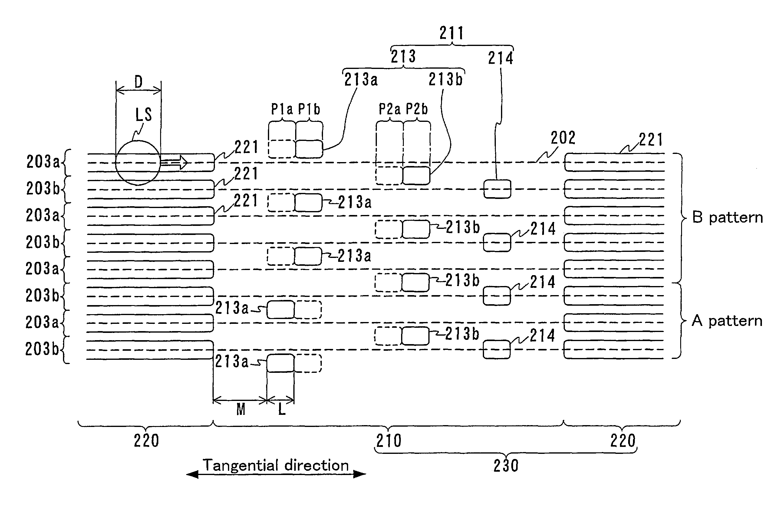
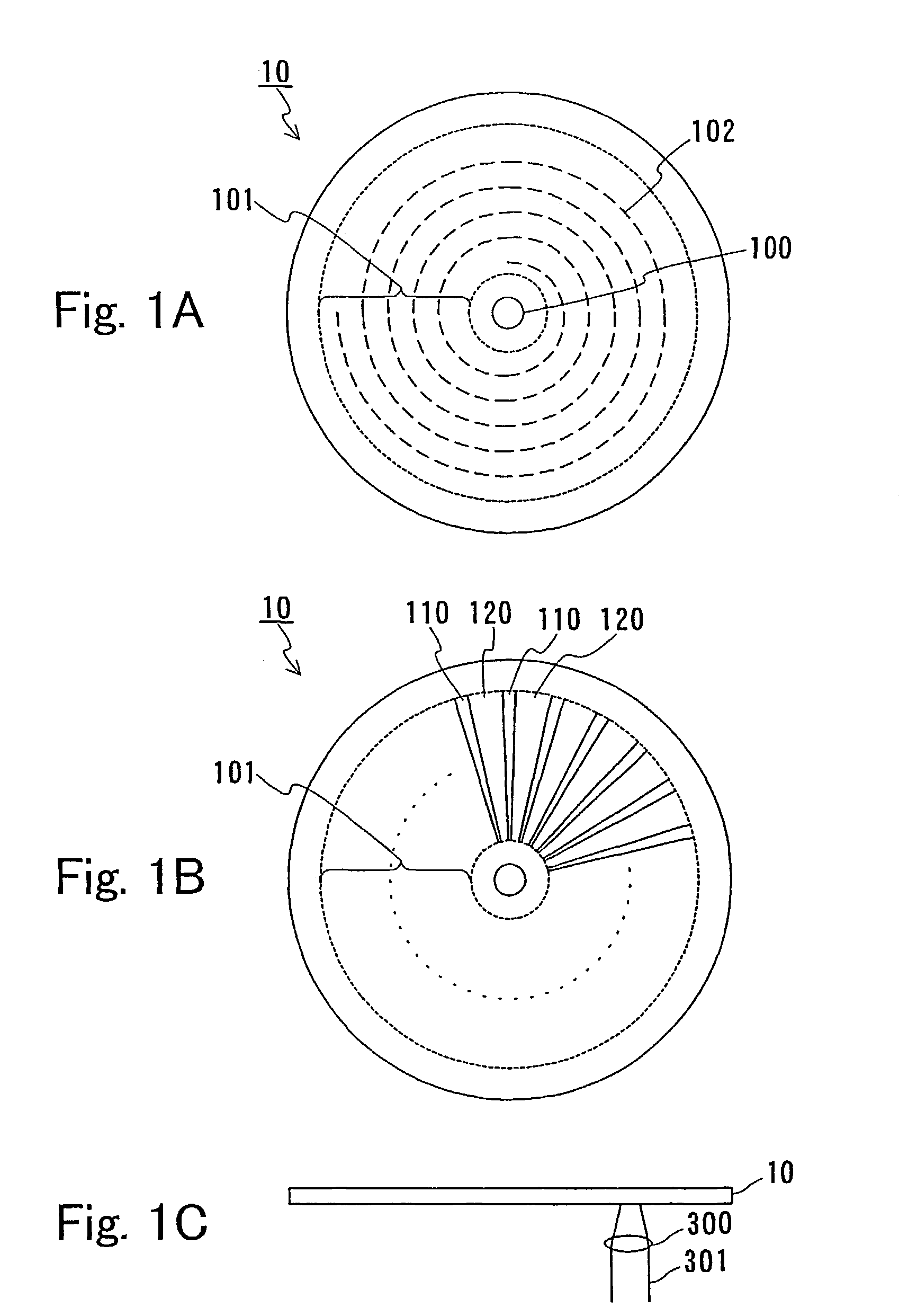
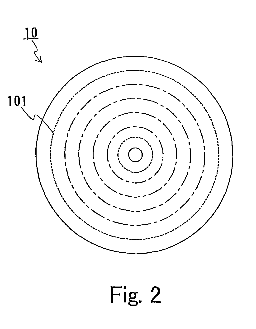
[0060]In Embodiment 1, a first information recording medium of the present invention will be described. The information recording medium of Embodiment 1 is irradiated with a laser beam condensed by an objective lens with a numerical aperture NA, whereby information is reproduced (or recorded). The information recording medium is provided with a disk-shaped substrate. On the surface of the substrate, a plurality of prepit regions and data regions are disposed alternately along spiral or concentric virtual track centers. The prepit region includes a pair of wobble pits for tracking servo. A length L (μm) of a wobble pit along the virtual track center and a spot diameter D (μm) of a laser beam along the virtual track center satisfy a relationship: 0.3≦(L / D)≦0.65. Particularly, it is preferable that L and D satisfy a relationship: 0.4≦(L / D)≦0.55. If the length of a wobble pit is within this range, even if the length of a wobble pit is varied, variations in an amplitude of a tracking con...

embodiment 2

[0069]In Embodiment 2, another information recording medium of the present invention will be described. The information recording medium of Embodiment 2 is irradiated with a laser beam condensed by an objective lens with a numerical aperture NA, whereby information is reproduced (or recorded). The information recording medium is provided with a disk-shaped substrate. On the surface of the substrate, a plurality of prepit regions and data regions are disposed alternately along spiral or concentric virtual track centers. The prepit region includes a pair of wobble pits for tracking servo. There are flat portions on the surface of the substrate before and after the wobble pits along the virtual track center. A length M (μm) of the flat portion along the virtual track center and a spot diameter D (μm) of a laser beam along the virtual track center satisfy a relationship: 0.65≦(M / D). When represented by using a wavelength λ (μm) of a laser beam to be radiated and a numerical aperture NA ...

embodiment 3

[0072]In Embodiment 3, a recording / reproducing method of the present invention will be described. According to a first recording / reproducing method of the present invention, the information recording medium of Embodiment 1 is irradiated with a laser beam condensed by an objective lens with a numerical aperture NA, whereby recording / reproducing is conducted. According to a second recording / reproducing method of the present invention, the information recording medium of Embodiment 2 is irradiated with a laser beam condensed by an objective lens with a numerical aperture NA, whereby recording / reproducing is conducted.

[0073]As a recording / reproducing apparatus used in the recording / reproducing method of the present invention, a general recording / reproducing apparatus can be used.

[0074]According to the first recording / reproducing method of the present invention, a length L (μm) of a wobble pit along a virtual track center, a wavelength λ (μm) of a laser beam, and a numerical aperture NA ...


PUM

PropertyMeasurementUnit
spot diameteraaaaaaaaaa
wavelengthaaaaaaaaaa
diameteraaaaaaaaaa

Abstract

An information recording medium for reproducing information by irradiation with a laser beam condensed by an objective lens with a numerical aperture NA includes a disk-shaped substrate and a recording layer disposed on the substrate. On the surface of the substrate, a plurality of prepit regions and a plurality of data regions are disposed alternately along spiral or concentric virtual track centers. Each prepit region includes a pair of wobble pits for tracking servo, and a length L (μm) of the wobble pit along the virtual track center, a wavelength λ (μm) of the laser beam, and a numerical aperture NA satisfy a relationship: 0.3≦L. NA / λ≦0.65.

Description

TECHNICAL FIELD[0001]The present invention relates to an information recording medium for reproducing information by irradiation with a laser beam, and a recording / reproducing method thereofBACKGROUND ART[0002]Recently, there is a demand for high-density optical disks, and the track pitch thereof is being narrowed while the linear density is being increased. In order to achieve a narrow track pitch, it is required to reduce interference with adjacent tracks such as cross-write. Therefore, it is important to conduct tracking control of a beam spot for recording / reproducing with good precision.[0003]As a method for controlling a beam spot, a push-pull tracking system is frequently used. However, this system has problems involved in a shift of an optical axis and a tilt of a disk.[0004]As a method for controlling a beam spot while reducing an error of tracking control even when fluctuations such as a shift of an optical axis occur, a sample servo tracking system is known. According to ...

Claims


Application Information

Patent Timeline
Patent Type & Authority Patents(United States)
IPC IPC(8): G11B11/105G11B11/00G11B7/013G11B7/09G11B7/26G11B7/007
CPCG11B7/0938G11B7/24085G11B11/10576G11B11/10578G11B7/00718G11B7/00745G11B7/261G11B7/013
Inventor HINO, YASUMORISHIOYA, MASAYOSHIHIRANO, KAZUMASAYUMITA, SHOHEI
Owner PANASONIC CORP
Why Eureka
Try Eureka