Susceptometers for foreign body detection

a susceptometer and foreign body technology, applied in the field of magnetic susceptometers, can solve the problems of difficult measurement of such a small response, significant problem in achieving similar stability at room temperature, and insufficient absolute response of the magnetic field sample, so as to facilitate quality control in interpretation.

Inactive Publication Date: 2005-11-15
KOPP DEV +1
View PDF49 Cites 10 Cited by
  • Summary
  • Abstract
  • Description
  • Claims
  • Application Information

AI Technical Summary

Benefits of technology

[0017]7. Using telemedicine to make the enhanced measurements widely availa

Problems solved by technology

The main challenge in such measurements is not only that the magnetic field response of the sample is small in absolute terms, but that the response may be many orders of magnitude smaller than the magnetic field that is applied to the specimen.
Measuring such a small response, in the presence of such a relatively large applied field, is especially difficult in a room-temperature instrument, because temperature fluctuations may distort the geometrical relationship between the magnets or coils that produce the applied magnetic field and the magnetic-field sensors that detect the response of the specimen.
This geometrical distortion causes fluctuations in the measured magnetic field, which can mask the desired magnetic field response

Method used


Image

  • Susceptometers for foreign body detection
  • Susceptometers for foreign body detection
  • Susceptometers for foreign body detection

Examples


Embodiment Construction

[0025]The features of several exemplary embodiments of the apparatus and methods of the present invention will now be described.

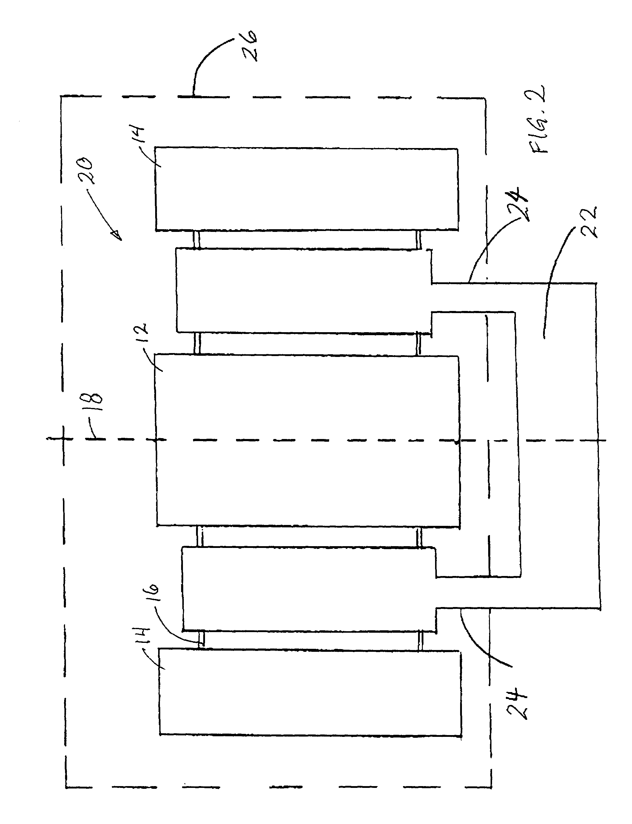
[0026]Exploiting symmetry in source-sensor unit configuration. One way to minimize the effects of thermal drifts in sensitive magnetic susceptibility measurements is to arrange the applied-field generating elements and magnetic sensors in a manner that (1) the signal due to the applied field is cancelled out and (2) the entire source-sensor unit is symmetrical, in such a way that the cancellation of the applied-field signal is preserved if the entire structure expands and contracts uniformly.

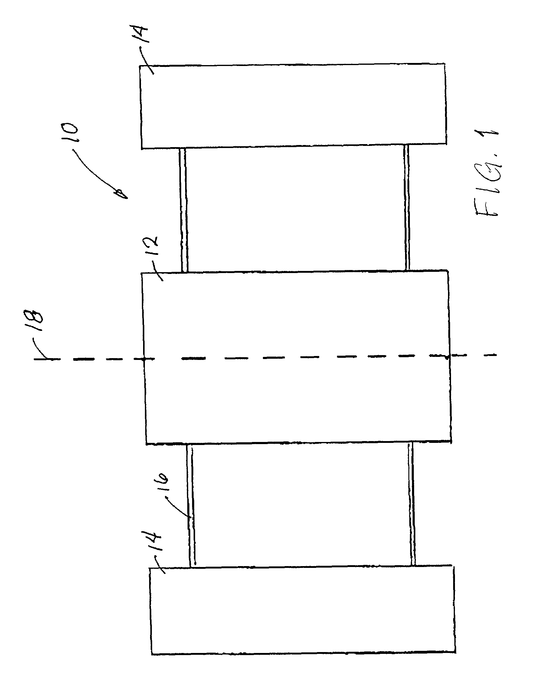
[0027]One example of this concept is shown in FIG. 1. In this preferred embodiment, the source-sensor unit 10 consists of an applied-field coil 12 and two identical sensor coils 14, co-axially wound on a single coil form 16, with the applied-field coil 12 centered between the two sensor coils 14. The sensor coils 14 are connected in series opposition to form a first-ord...


PUM


Abstract

Methods and apparatus for minimizing the effects of temperature drift in a magnetic susceptibility measurement instrument, such as an instrument used in pre-MRI screening for the presence of ferromagnetic foreign bodies. The magnetic field source and magnetic sensors can be combined into a single, rigid unit. The stability and sensitivity required in high quality magnetic susceptibility measurements can be achieved through symmetrical design of the source-sensor unit, minimization of thermal stresses, minimization of temperature variations, use of materials with low thermal expansion coefficients, or through appropriate combinations thereof. Use of patient eye movement where an eye is being screened, use of a water bag between the patient and the instrument, or use of telemedicine to facilitate performance of the necessary computations can also be incorporated.

Description

CROSS REFERENCE TO RELATED APPLICATIONS[0001]This is a continuation-in-part patent application of U.S. patent application Ser. No. 09 / 741,774, filed on Dec. 15, 2000 now U.S. Pat. No. 6,418,335, and entitled “Ferromagnetic Foreign Body Detection Using Magnetics”, which is a continuation patent application of U.S. patent application Ser. No. 09 / 135,890, filed on Aug. 18, 1998, and entitled “Noninvasive Room Temperature Instrument to Measure Magnetic Susceptibility Variations in Body Tissue”, now U.S. Pat. No. 6,208,884, which was a continuation-in-part application of U.S. patent application Ser. No. 08 / 670,393, filed on Jun. 25, 1996, and entitled “Ferromagnetic Foreign Body Screening Method and Apparatus”, now U.S. Pat. No. 5,842,986, the disclosures of which are incorporated herein by reference. This is also a continuation-in-part patent application of co-pending U.S. patent application Ser. No. 09 / 818,700, filed on Mar. 27, 2001, and entitled “Simplified Water Bag Technique for Ma...

Claims


Application Information

Patent Timeline
IPC IPC(8): A61B5/05A61B5/04G01V3/08G01R33/16
CPCA61B5/04005A61B5/05G01R33/16G01V3/08A61B5/242
Inventor AVRIN, WILLIAM F.KUMAR, SANKARANCZIPOTT, PETER V.MCCLURE, RICHARD J.MASSENGILL, R. KEMP
Owner KOPP DEV
Why Eureka
Try Eureka