Method and apparatus for two dimensional surface property analysis based on boundary measurement

a two-dimensional surface and boundary measurement technology, applied in the direction of material analysis, resistance/reactance/impedence, instruments, etc., can solve the problems of prohibitive cost and effort required to cover a significant surface area of a structure with resistance strain gauges, and may be impractical in many applications

Inactive Publication Date: 2005-11-15
BATTELLE ENERGY ALLIANCE LLC
View PDF9 Cites 48 Cited by
  • Summary
  • Abstract
  • Description
  • Claims
  • Application Information

AI Technical Summary

Problems solved by technology

However, strain gauges typically cover only a small area of the structure.
The cost and effort required to cover a significant surface area of a structure with resistance strain gauges may be prohibitive.
Additionally, a technique using multiple strain gauges would likely require the presence of conductive, such as wire, leads extending to each strain gauge distributed across the surface to be observed, which may be impractical in many applications.
However, like a strain gauge implementation, the Ortiz patent requires wire leads attached to measurement points distributed throughout the surface of the structure, which may be impractical in many applications.
Unfortunately, these solutions are typically volumetric solutions requiring the object to be somewhat conductive throughout the volume of the object.
Thus, for analysis concerned with the surface characteristics of an object, these electrical impedance tomography techniques are generally inadequate.

Method used


Image

  • Method and apparatus for two dimensional surface property analysis based on boundary measurement
  • Method and apparatus for two dimensional surface property analysis based on boundary measurement
  • Method and apparatus for two dimensional surface property analysis based on boundary measurement

Examples


Embodiment Construction

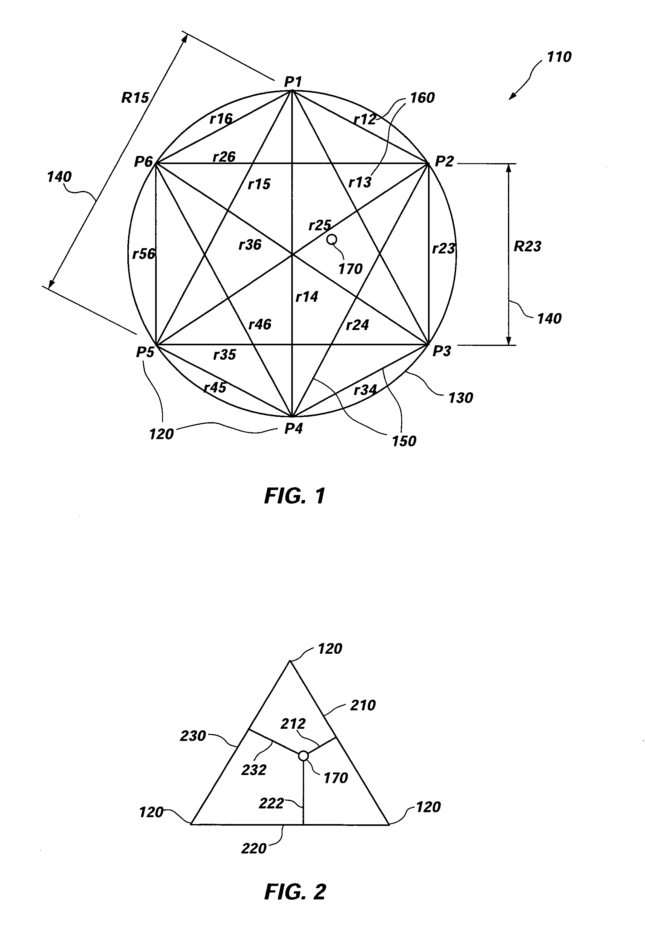
[0023]An exemplary embodiment of the present invention includes a method of analyzing resistance, or other physical properties, of a conductive film 110. As shown in FIG. 1, a plurality of probe locations 120 may be selected around the periphery 130 of the conductive film 110. The probe locations 120 may be selected in a manner allowing one or more areas of interest, where property analysis is desired to be encompassed within a boundary defined by line segments extending between each of the adjacent probe locations 120. For example, in FIG. 1, with N(six) probe locations 120, the boundary is defined by six line segments (i.e., line segment P1–P2, line segment P2–P3, line segment P3–P4, line segment P4–P5, line segment P5–P6, and line segment P6–P1).

[0024]As a result of selection of the probe locations 120, an analysis mesh is defined by line segments, also referred to as measurement lines 150, between each probe location and all other probe locations 120 in the plurality of probe lo...


PUM

PropertyMeasurementUnit
conductiveaaaaaaaaaa
electrical resistanceaaaaaaaaaa
electrical resistancesaaaaaaaaaa

Abstract

An apparatus and method for determining properties of a conductive film is disclosed. A plurality of probe locations selected around a periphery of the conductive film define a plurality of measurement lines between each probe location and all other probe locations. Electrical resistance may be measured along each of the measurement lines. A lumped parameter model may be developed based on the measured values of electrical resistance. The lumped parameter model may be used to estimate resistivity at one or more selected locations encompassed by the plurality of probe locations. The resistivity may be extrapolated to other physical properties if the conductive film includes a correlation between resistivity and the other physical properties. A profile of the conductive film may be developed by determining resistivity at a plurality of locations. The conductive film may be applied to a structure such that resistivity may be estimated and profiled for the structure's surface.

Description

CONTRACTUAL ORIGIN OF THE INVENTION[0001]This invention was made with United States Government support under Contract No. DE-AC07-99ID13727 awarded by the United States Department of Energy. The United States Government has certain rights in the invention.BACKGROUND OF THE INVENTION[0002]1. Field of the Invention[0003]The present invention relates to nondestructive material evaluation and, in particular, to a method for characterizing and evaluating integrity and physical properties of electrically conducting material structures.[0004]2. Description of Related Art[0005]Structures and the materials comprising those structures are often evaluated for integrity and other physical properties using a variety of nondestructive evaluation techniques. These techniques include thermographic, optical, acoustic, radiographic (e.g., x-ray), and electromagnetic procedures.[0006]Electrical impedance measurement and analysis of structures and their surfaces is of particular interest because often,...

Claims


Application Information

Patent Timeline
Patent Type & Authority Patents(United States)
IPC IPC(8): G01R13/00G01R13/02G06F19/00G01N27/04
CPCG01N27/041
Inventor RICHARDSON, JOHN G.
Owner BATTELLE ENERGY ALLIANCE LLC
Why Eureka
Try Eureka