Dynamic partitioning of memory banks among multiple agents

a technology of memory bank and agent, applied in the direction of memory address/allocation/relocation, instruments, computing, etc., can solve the problems of reducing the overall speed of accesses, limiting the design of conventional systems using synchronous memory, and clock signals from separate agents not being conventionally synchronous or in phase with one another

Inactive Publication Date: 2005-11-15
AGERE SYST INC
View PDF26 Cites 79 Cited by
  • Summary
  • Abstract
  • Description
  • Claims
  • Application Information

AI Technical Summary

Problems solved by technology

Unfortunately, the clock signals from separate agents are not conventionally synchronous or in phase with one another.
There are limitations to conventional system designs using synchronous memory.
Wait states decrease the overall speed of accesses to the synchronous memory 508 and result in decreased performance.
However, in practice, the synchronous memory blocks 508a, 508b are less than fully utilized, thus wasting memory.
Moreover, if a particular use or application of the device uses one agent but not others, the memory pre-defined for use by the unused agent is wasted.

Method used


Image

  • Dynamic partitioning of memory banks among multiple agents
  • Dynamic partitioning of memory banks among multiple agents
  • Dynamic partitioning of memory banks among multiple agents

Examples


first embodiment

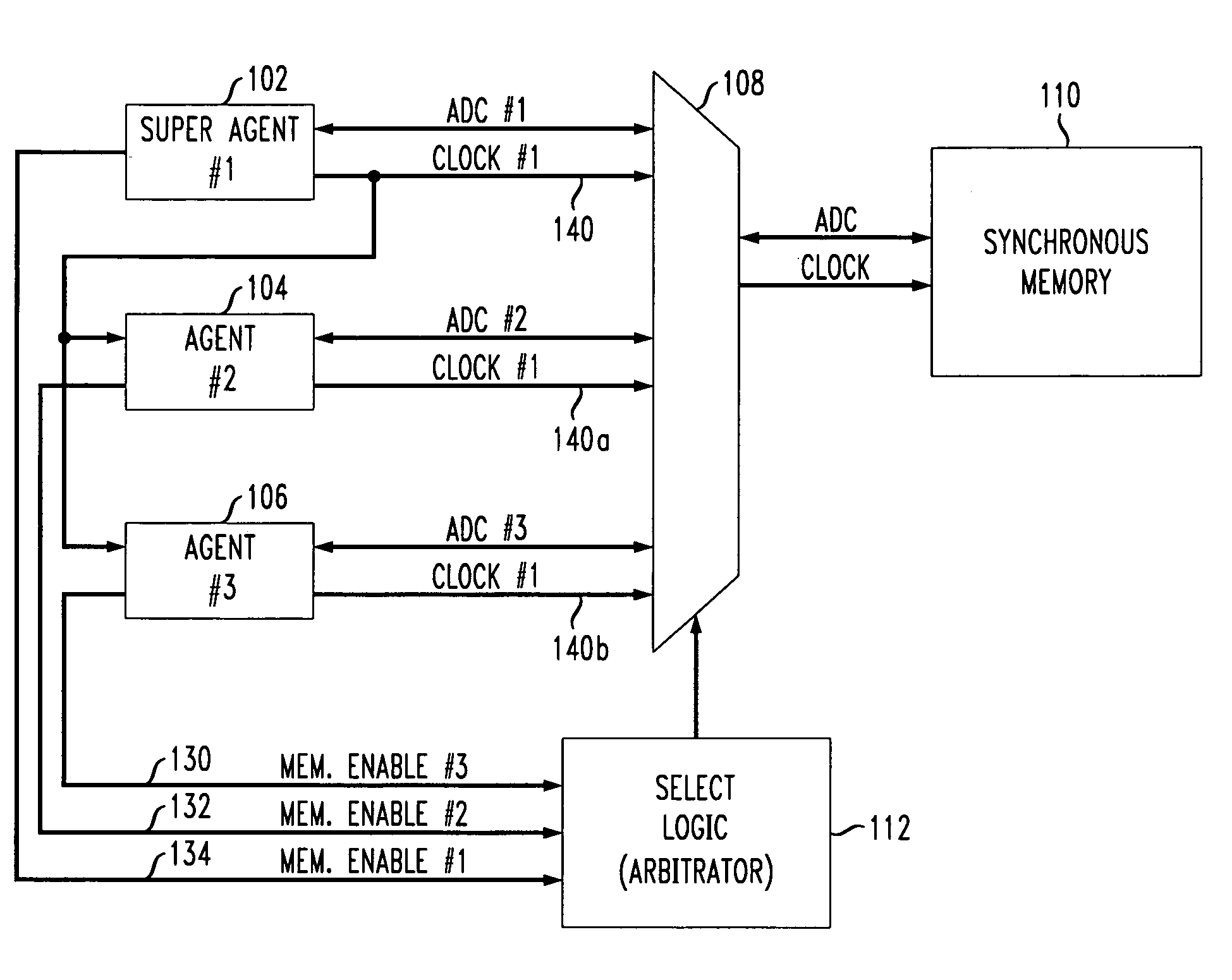
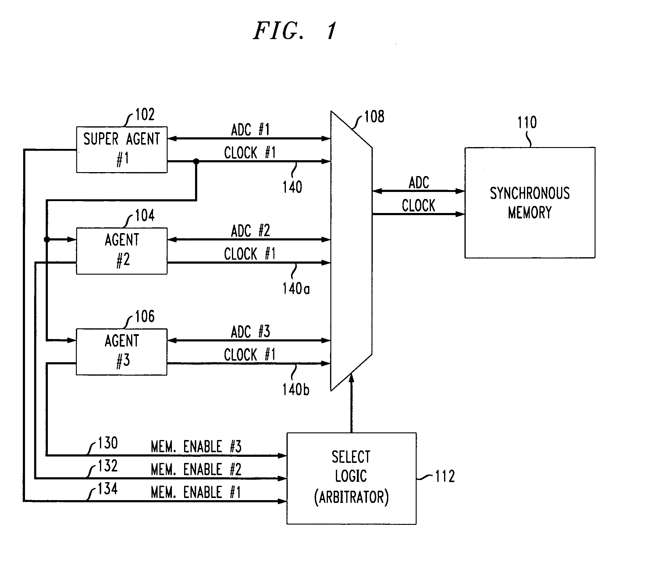
[0033]FIG. 1 shows a first aspect of the present invention wherein a multiple agent system has one or more agents which utilize a clock signal from a super agent to synchronize clock signal access timing to the shared synchronous memory.

[0034]In particular, a synchronous memory block 110 is accessed by a plurality of agents 102–106 as shown in FIG. 1. Although three agents 102–106 are shown in FIG. 1, the present invention relates to multiple agent systems having any number of agents accessing shared memory.

[0035]An appropriately sized multiplexer (MUX) 108 forms a switch which allows any one of the multiple agents 102–106 to access the shared synchronous memory 110. The relevant busses for each agent 102–106 include the address, data and control (ADC) busses and a clock signal.

[0036]The MUX 108 is controlled by selecting logic, i.e., an arbitrator 112. The arbitrator 112 is provided with respective memory request signals 130–134 from each of the accessing agents 102–106, and based ...

second embodiment

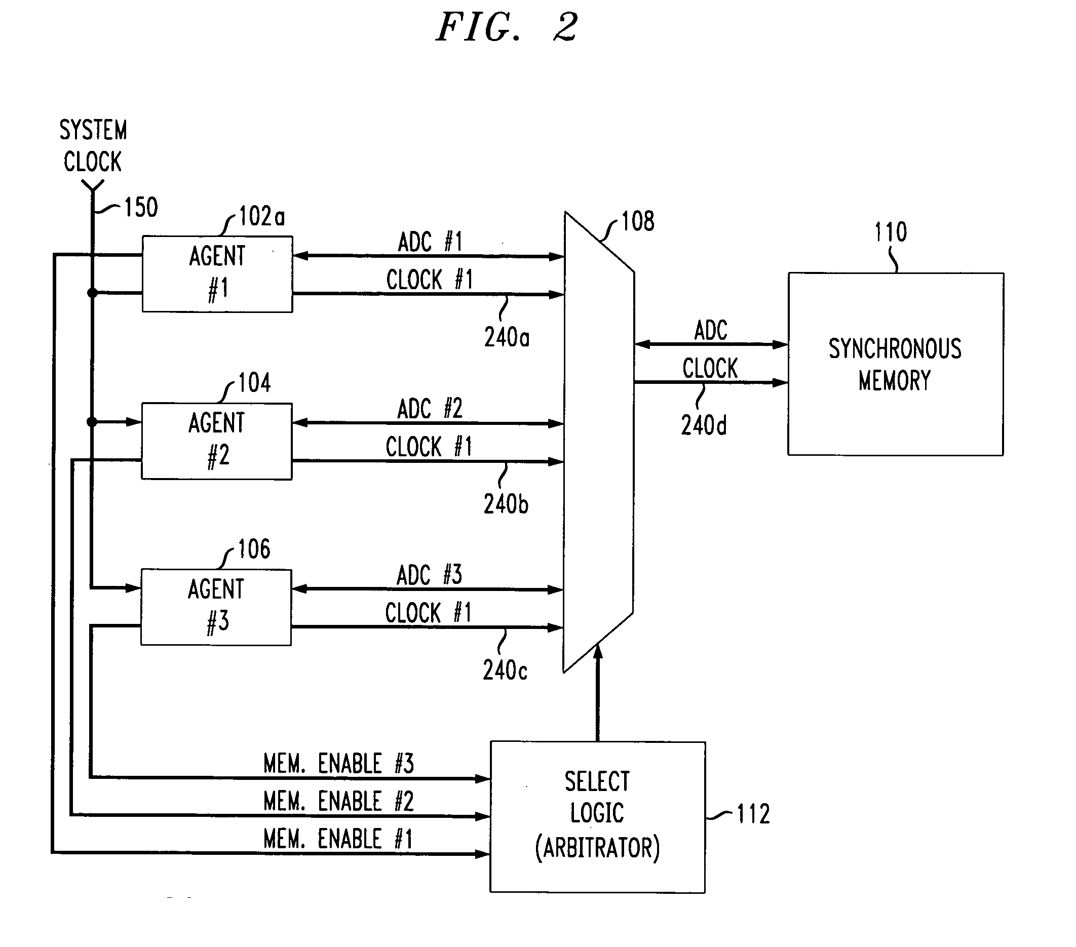
[0042]FIG. 2 shows the first aspect of the present invention wherein all agents 102a, 104 and 106 are non-super agents using a shared system clock signal 150 to synchronize clock signal access timing to the shared synchronous memory 110.

[0043]In particular, the shared synchronous memory 110 may be conventional and is as described and shown with respect to the embodiment of FIG. 1. Moreover, the MUX 108, arbitrator 112 and non-super agents 104, 106 are as described and shown with respect to FIG. 1. In this embodiment, however, the super-agent 102 shown in FIG. 1 is replaced with a non-super agent 102a.

[0044]All three agents 102–106 receive a system level clock signal 150 to which respective address, data and control busses as well as respective memory access clock signals 240a–240c are synchronized. Thus, the clock signal 240d provided to the shared synchronous memory 110 is synchronized, e.g., has the same frequency, duty cycle and / or phase with respect to the clock signals 240a, 2...


PUM


Abstract

A multiple agent system providing each of a plurality of agents, e.g., processors, to access a shared synchronous or asynchronous memory. In the case of synchronous memory, the clock signal from a super agent selected from among the plurality of agents provides a memory access clock signal to the other agents accessing the same shared memory. The other agents synchronize their respective address, data and control busses to those of the super agent, and output a representation of the same clock signal to the shared memory. In another aspect of the present invention, the shared memory is partitioned for use from among a plurality of groups of agents, each agent group comprising one or more agents. Any one of the agents may update a configuration register to flexibly reconfigure the amount of shared memory available to the agents as necessary.

Description

[0001]This application claims priority from U.S. Provisional Application No. 60 / 065,855 entitled “Multipurpose Digital Signal Processing System” filed on Nov. 14, 1997, the specification of which is hereby expressly incorporated herein by reference.BACKGROUND OF THE INVENTION[0002]1. Field of the Invention[0003]This invention relates generally to the shared usage of memory by a plurality of agents, i.e., processors. In particular, in one aspect it relates to the efficient use of shared synchronous memory by a plurality of agents, and in another aspect it relates to the flexible partitioning of shared memory between a plurality of agents.[0004]2. Background of Related Art[0005]With the ever-increasing speeds of today's processors, memory designs have attempted to meet the required speed requirements. For instance, synchronous memory such as synchronous static random access memory (SSRAM) and synchronous dynamic random access memory (SDRAM) are commonly available synchronous types of ...

Claims


Application Information

Patent Timeline
Patent Type & Authority Patents(United States)
IPC IPC(8): G06F12/00G06F12/06
CPCG06F12/0607
Inventor BAYS, LAURENCE EDWARDFADAVI-ARDEKANI, JALILGUTTA, SRINIVASAKERMANI, BAHRAM GHAFFARZADEHNIESCIER, RICHARD JOSEPHSMITH, GEOFFREY LAWRENCESOTO, WALTER G.GREENWOOD, DANIEL K.
Owner AGERE SYST INC
Why Eureka
Try Eureka