Seeding tool

a technology for seeding tools and tools, applied in the field of seeding tools, can solve the problems of short wear life, difficulty in repairing when worn, and damage to fertilizers

Inactive Publication Date: 2005-11-22
KENNAMETAL INC +1
View PDF21 Cites 15 Cited by
  • Summary
  • Abstract
  • Description
  • Claims
  • Application Information

AI Technical Summary

Benefits of technology

[0011]The present invention provides a seeding tool, and particularly a single-pass seeding tool which can concurrently dispense seeds and fertilizer into a generally v-shaped furrow created by the seeding tool, wherein the fertilizer is maintained a critical distance from the seeds. The seeding tool comprises a rear frame member, a front knife opener, associated seed and fertilizer dispensing members, and a liquid wing insert affixed to the side of the knife opener. The liquid wing insert can provide and maintain critical separation between the seed and the fertilizer, and also protect the end of the fertilizer tube from wear and becoming plugged with soil.
[0012]The knife opener includes a narrow top including furrowing tip, opposite side faces and a bottom. A tungsten carbide tip can be secured to the furrowing tip of the knife opener. The fertilizer dispensing member can be a tube which extends through the rear frame member towards the bottom of the knife opener. The end of the fertilizer tube can terminate outward from, and generally perpendicular to, one side of the knife opener. The knife opener can have a liquid wing insert according to the present invention affixed on the side thereof proximate the end of the fertilizer tube. The liquid wing insert is positioned forward of the fertilizer tube and can have a shape which, when affixed to the side of the knife opener, projects sufficiently outward from the side thereof to protect the end of the fertilizer tube.
[0013]The liquid wing insert can preferably be made from tungsten carbide, or a ceramic material and the size and shape thereof can be designed to perform several functions. For example, the liquid wing insert must extend from the side of the knife opener sufficiently to both shield the end of the fertilizer tube from the soil and to create and maintain critical spacing between the seeds and the fertilizer. The shape of the liquid wing insert can also be designed with aerodynamic considerations in mind, such as to provide minimal resistance while the insert is drawn through the soil on the side of the knife opener.

Problems solved by technology

Dispensing the fertilizer such that it comes into contact with or is deposited too close to the seeds can result in the fertilizer damaging and / or destroying the seeds.
Some disadvantages of the conventional liquid wing protrusion can include an undesirably short wear life, difficulty in repairing when worn, and less than optimum shape characteristics resulting from the hard-facing process.
Even the hard-facing of the integrally cast liquid wing member can be insufficient to provide the desired wear resistance.
If the knife opener is utilized with an overly worn wing protrusion, problems will almost certainly occur, including deposition of the fertilizer too close to the seeds, thus destroying or damaging the seeds, and rapid wear and frequent plugging of the fertilizer tube.
The conventional way to rebuild the liquid wing on the side of the knife opener is by depositing hard facing or welding material on the side of the knife opener to rebuild the wing shaped protrusion, which can be a difficult and time consuming process.
This type of repair can also result in a shape which can be even less desirable than the original post hard-faced liquid wing member.
However, this hard-facing process can also result in a blurring of the original cast shape of the liquid wing, making the final shape of the liquid wing less than desirable.
Reconstituting a worn liquid wing member by laying down weldment can result in an even less optimal shape.

Method used


Image

  • Seeding tool
  • Seeding tool
  • Seeding tool

Examples


Embodiment Construction

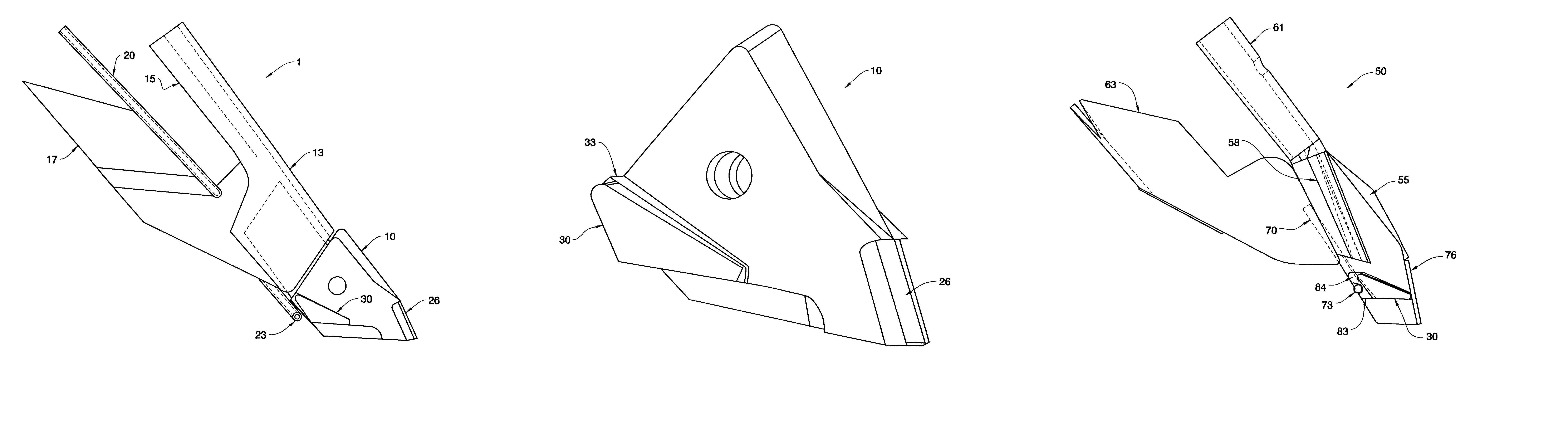
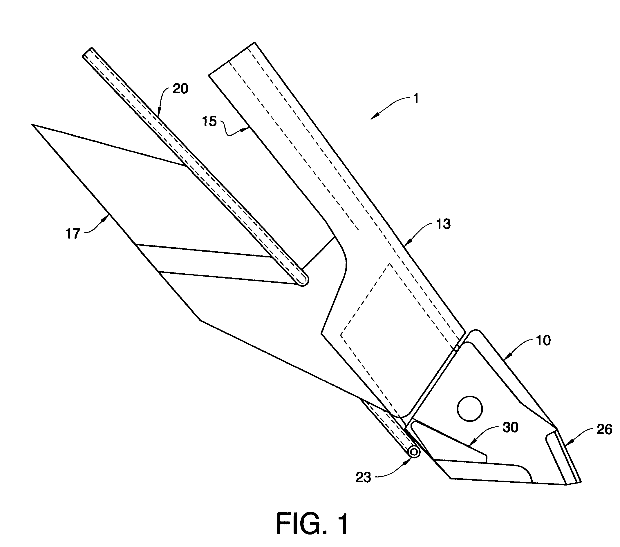
[0030]Referring now to the drawings, which are for purposes of illustrating the invention only, and not for purposes of limiting the same, a seeding tool 1 is shown in FIG. 1 having a removable knife opener 10 and a tungsten carbide liquid wing insert 30 affixed to the side thereof. The seeding tool 1 can be one component of a modular seed planting system 90, as shown in FIG. 19. The seed planting system 90 can include a seeding tool, such as the seeding tool 1 (FIG. 1), having a frame member 13 for securing to a shank 2. A plurality of seeding tools 1 and shanks 2 can typically be attached to a tillage implement 7 having one or more tool bars 92. As shown, a plurality of seeding tools 1 can be attached to spaced apart locations on each toolbar 92. The spaced arrangement is selected to allow the best passage of field trash between adjacent seeding tools 1, yet minimize soil ridging. For example, but not limited to, the seeding tools 1 can be spaced transversely to each other or in a...


PUM


Abstract

A seeding tool for depositing seeds and fertilizer within a furrow including a knife opener having a liquid wing projecting from the side thereof for providing and maintaining spacing between the seeds and fertilizer. Preferably, the liquid wing is a tungsten carbide insert secured to the side of the knife opener, and has a wing shaped structure which is shaped and sized to space the fertilizer apart from the seeds, to protect the end of the tube from which fertilizer is dispensed, and to present a small leading surface which displaces the soil easily and presents minimal resistance. Preferably, the largest, side surface of the liquid wing insert is inclined toward the side of the knife opener from a widest lower, rear member adjacent the end of the fertilizer tube to a narrower top, front member near a leading end of the knife opener.

Description

BACKGROUND OF THE INVENTION[0001]1. Field of the Invention[0002]The present invention relates to a seeding tool, including a liquid wing member that facilitates single pass planting and fertilizing of seeds. The liquid wing insert of the present invention includes a tungsten carbide insert rigidly attached to a knife opener of the seeding tool. The liquid wing insert can be brazed or glued to the knife opener and can provide increased wear life of the knife opener.[0003]2. Description of the Background Art[0004]The agricultural industry is employing larger and more efficient single pass planting systems for minimal tillage planting. Such systems can employ a seeding tool having a removable knife opener, which breaks the soil and creates a generally v-shaped trough into which seeds are dispensed. The knife opener can include integral or attachable members which can facilitate the concurrent dispensing of the seeds at the proper depth and the fertilizer at the proper distance from the...

Claims


Application Information

Patent Timeline
Patent Type & Authority Patents(United States)
IPC IPC(8): A01C5/00A01C5/06A01C7/06A01C7/00
CPCA01C5/062A01C7/06
Inventor ROWLETT, DON C.YEAGER, LINUS I.BIGELOW, DEAN M.
Owner KENNAMETAL INC
Why Eureka
Try Eureka