Shank installation structure and cutters

Inactive Publication Date: 2005-11-22
MIYANAGA KK
View PDF20 Cites 26 Cited by
  • Summary
  • Abstract
  • Description
  • Claims
  • Application Information

AI Technical Summary

Benefits of technology

[0035]Yet further, in the cutter according to the sixth invention, if the engaging portion is a conical concave portion, such an arrangement is a preferred embodiment for convenience of work because it can be easily worked with a drill or the like.
[0036]In each of the foregoing

Problems solved by technology

Such a screw-locking type shank attaching structure, however, offers a low operability because it requires that the screw be loosened and fastened for detachment and attachment of cutters with use of a tool such as a hexagonal wrench at every change of the diameter of a hole to be drilled.
For this reason, the chip breaking mechanism does not function effectively and hence cannot break strip-shaped chips produced during a cutting operation.
The construction of this portion is intricate, which increases a parts count.
Further, since the shank attaching structure needs to be assembled while positioning the supporting member urged to spring out of the shank attaching bore toward the opening thereof and the sprin

Method used


Image

  • Shank installation structure and cutters
  • Shank installation structure and cutters
  • Shank installation structure and cutters

Examples


Example

[0054]Hereinafter, a shank attaching structure and a cutter having a shank for use with the attaching structure according to an embodiment of the present invention will be described specifically with reference to the drawings. However, the present invention is not limited to this embodiment.

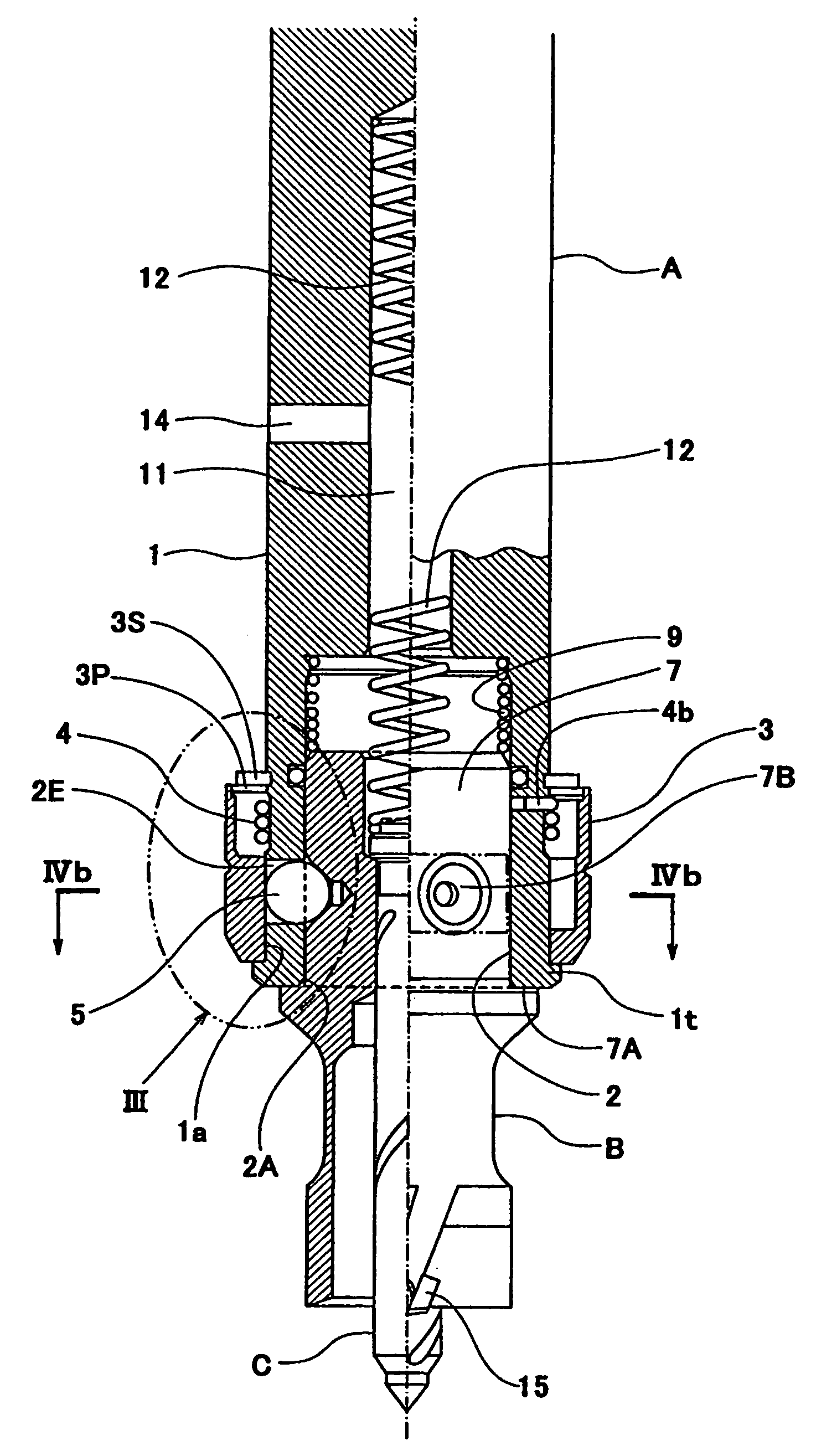
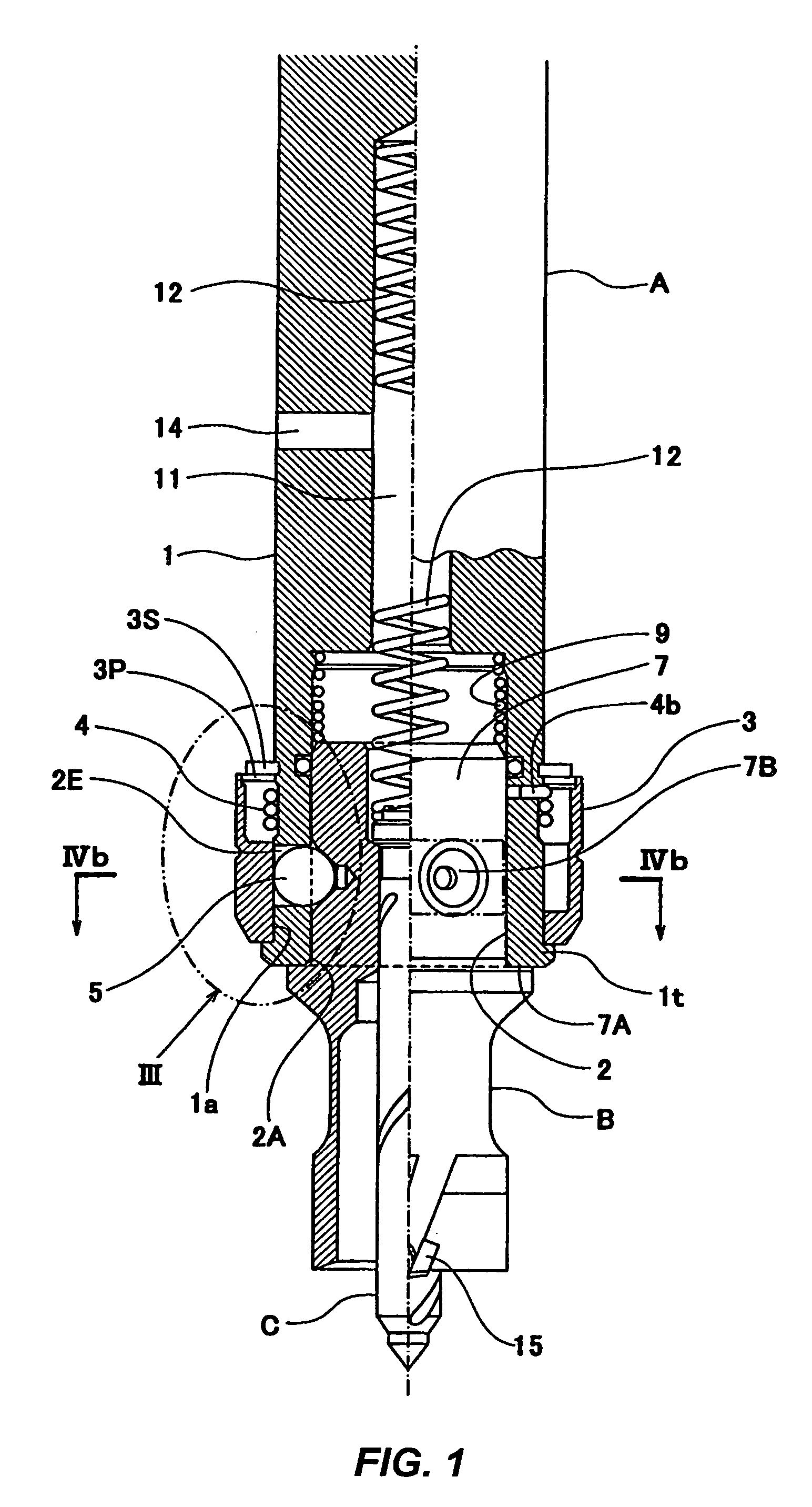
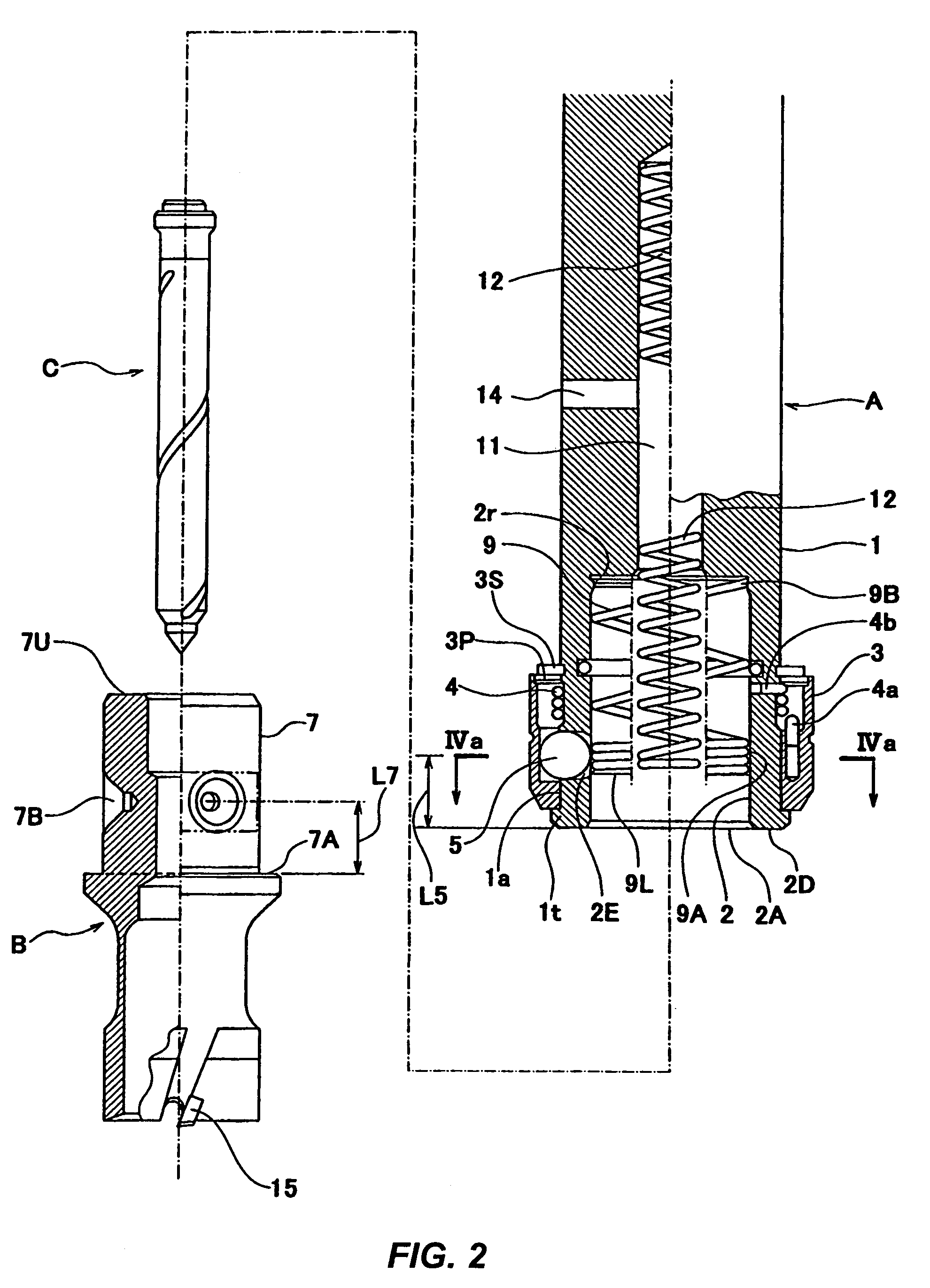
[0055]In FIGS. 1 and 2 showing this embodiment, A designates an arbor secured to the drilling apparatus side, B designates a cutter having a base end provided with a shank 7 to be attached to and detached from the arbor A and a tip provided with a cutting edge 15, C designates a center pin for positioning the cutter B at the time of drilling, serving as an on-off valve for the supply of a coolant, and discharging core-shaped cut-out chips from the inside of the cutter.

[0056]As shown in FIG. 1 or 2, the arbor A has an opening 2A of a shank attaching bore 2 at a tip (the lower end in FIGS. 1 and 2) of an arbor body 1. On an outer peripheral portion of the arbor body 1 adjacent the base end of the o...


PUM

PropertyMeasurementUnit
Electric chargeaaaaaaaaaa
Digital informationaaaaaaaaaa
Diameteraaaaaaaaaa

Abstract

A shank attaching structure with as less axial free movement as possible and of a simplified construction, a cutter for use with the shank attaching structure, and a cutter for use with the shank attaching structure which is free from an incident that the cutter becomes incapable of coming off even if an impactive rotating torque is exerted thereon, are intended to be provided, wherein the shank attaching structure is constructed such that in a state restricted by a restriction mechanism for restricting a depth to which a shank (7) is inserted into an arbor (A), the position of an engaging portion (7B) relative to the lock member (5) is axially deviated toward the open side of a shank attaching bore to bring the lock member (5) and the engaging portion (7B) into abutment with each other on the base end side of the shank attaching bore. The cutter (B) is constructed such that an outer peripheral edge portion (7C) of a concave portion forming the engaging portion (7B) is dented from an outer peripheral surface of the shank (7).

Description

TECHNICAL FIELD[0001]The present invention relates to a shank attaching structure capable of attaching a shank to an arbor on a drilling apparatus side with one touch, that is, quickly and easily, as well as to a cutter (meant by a broad concept including not only a cutter in a narrow sense but also a drill, and further including an adapter to be attached to a base end of a cutter) having a suitable shank for use with that shank attaching structure.BACKGROUND ART[0002]Heretofore, there has been a shank attaching structure of the so-called “screw-locking type” adapted to secure the shank of a cutter to an arbor attached at its base end to a rotating shaft of a drilling apparatus (an electric hand drill or a drilling machine) by side locking with a screw. At present, this screw-locking type shank attaching structure is most prevalent on a worldwide scale. Such a screw-locking type shank attaching structure, however, offers a low operability because it requires that the screw be loosen...

Claims


Application Information

Patent Timeline
IPC IPC(8): B23B31/10B23B31/107B23B51/04B23Q3/12
CPCB23B31/1071B23B51/0426B23B51/0473Y10T408/953Y10T408/895Y10T279/17752Y10T279/3481
Inventor MIYANAGA, MASAAKI
Owner MIYANAGA KK
Why Eureka
Try Eureka