Electromechanical connector

a technology of electromechanical connection and connector, which is applied in the direction of electrically conductive connection, coupling device connection, electrical apparatus, etc., can solve the problems of short circuit, component destruction, contact elements or contact poles that cannot be reversed, etc., and achieve the effect of fast and precise separation

Inactive Publication Date: 2005-11-22
BULLINGER ACHIM +1
View PDF13 Cites 127 Cited by
  • Summary
  • Abstract
  • Description
  • Claims
  • Application Information

AI Technical Summary

Benefits of technology

[0012]The elevation has the effect that very fast and precise separation occurs during disengagement, which is generally performed by a slight rotation of the switching mechanism and tripping mechanism relative to one another, with the result that the current is likewise interrupted very quickly and precisely.
[0013]A simple solution which aids rotation during detachment of the switching mechanism from the tripping mechanism can consist in that the partial annular bead is provided with the elevation and in that the trough is formed in the partial annular groove.
[0014]In this configuration, it is possible in a simple way to provide the partial annular bead with the elevation and to form the trough correspondingly in the partial annular groove.

Problems solved by technology

This means that the contact elements or contact poles cannot be reversed.
Otherwise there would be short circuits and associated destruction of components.

Method used


Image

  • Electromechanical connector
  • Electromechanical connector
  • Electromechanical connector

Examples


Embodiment Construction

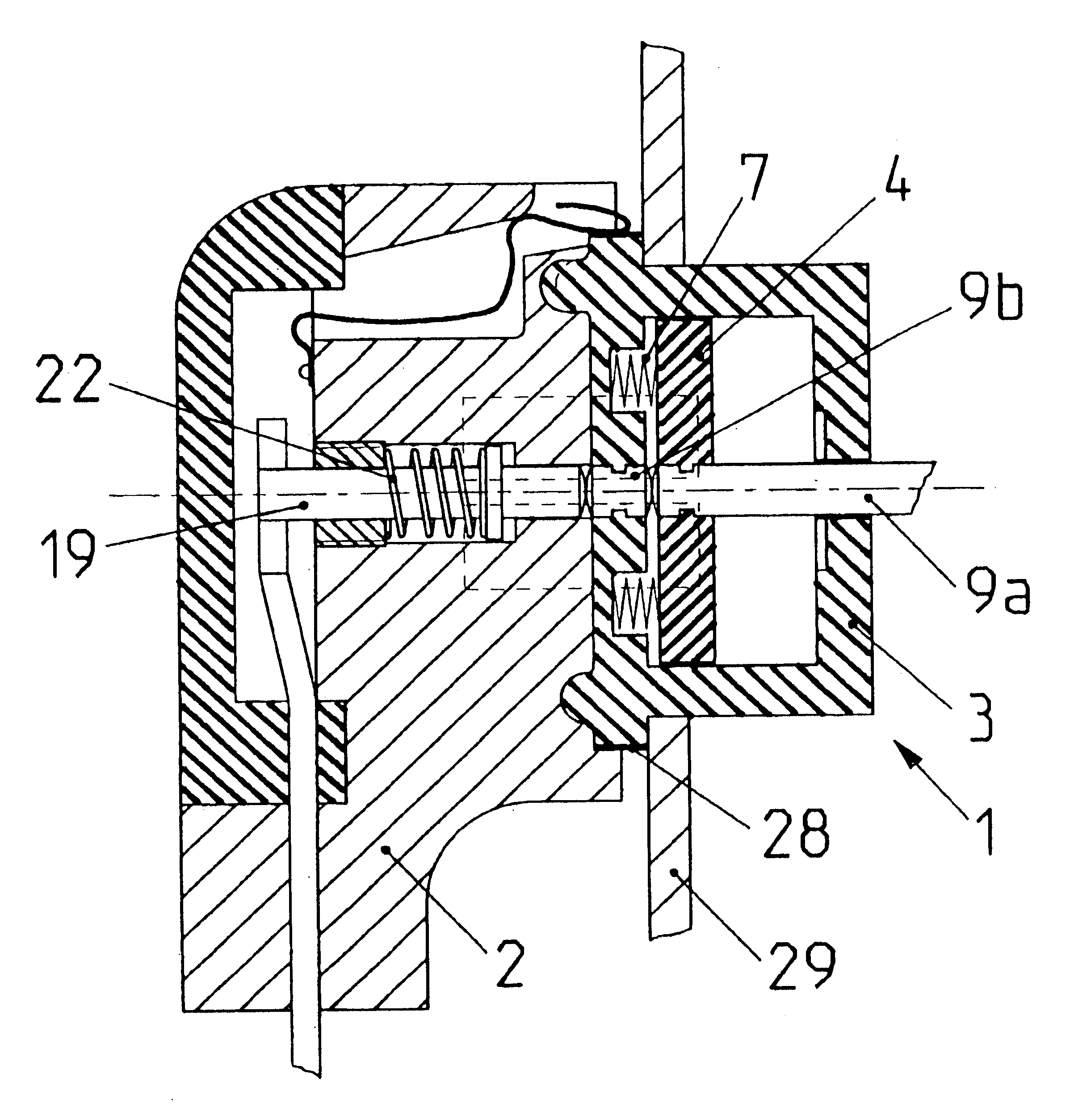
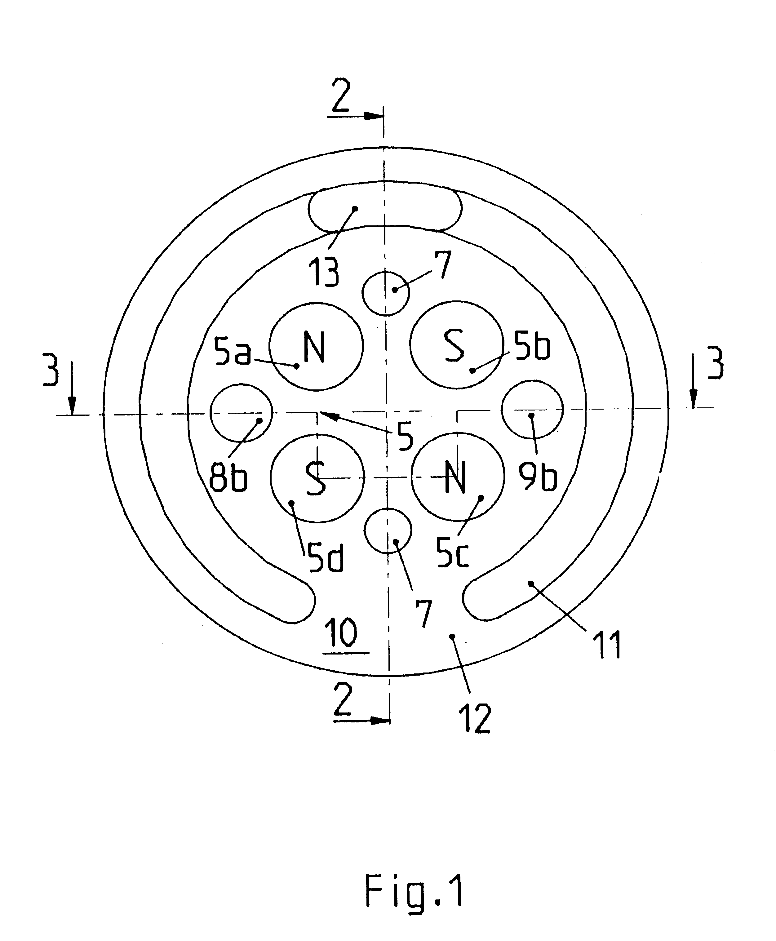
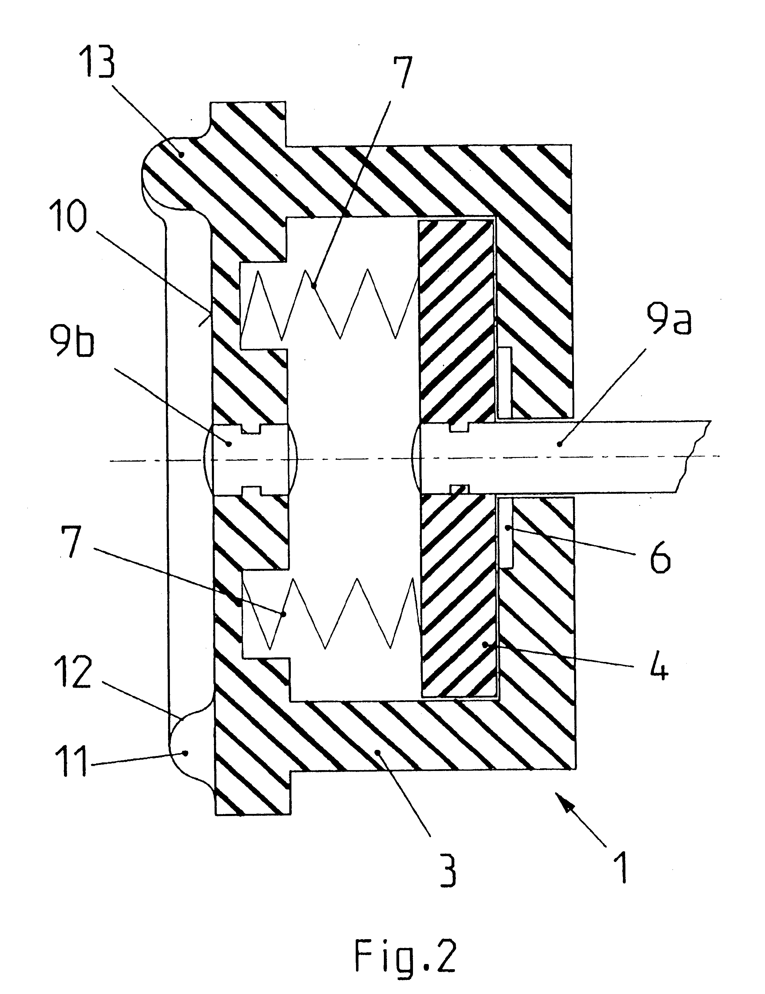
[0023]Two coaxial contact parts 8a and 8b for the positive pole and, contact parts 9a and 9b for the negative pole are provided in each case as contact elements in the switching mechanism 1. The contact parts 8a and 9a are arranged on the operating slide 4 or connected thereto, and simultaneously also make the respective contact wiht the supply leads to the switching mechanism 1. The contact parts 8b and 9b are located in the end face 10, directed toward the tripping mechanism, or the switching mechanism 1. However, they are separated from the coded magnet parts 5a-5d.

[0024]The embodiment represented is suitable, in particular, for the low-voltage range, for example 12 volts, and for direct current. Of course, however, it is also suitable in principle for higher voltages and also for alternating current.

[0025]With reference to their design principle and to the fact that they are switched via coded magnets, the switching mechanism 1 and the tripping mechanism 2 are designed in a sim...


PUM


Abstract

The electromechanical connector proposed has a switch and an actuator. The switch can be connected by means of contacts to a power supply and has switching magnets with encoded magnetic elements mounted on a carriage. It is fitted in a housing as an enclosed unit. The actuator has actuation magnets with encoded magnetic elements and can be connected to a consumer. The switch can be connected to the actuator, connecting these two devices causing the switching magnets to move, against a restraining force, from an inoperative position to an operating position. The electrical connection between the switch and the actuator is thus established by means of contacts. The ends of the switch and actuator facing each other are fitted with alignment devices designed so that electrical contact between the switch and the actuator can only be made when the contacts are in a particular position with respect to each other.

Description

CROSS-REFERENCES TO RELATED APPLICATIONS[0001]Not applicable.STATEMENT REGARDING FEDERALLY SPONSORED RESEARCH & DEVELOPMENT[0002]Not applicable.BACKGROUND OF THE INVENTION[0003]The invention relates to an electromechanical connecting device according to the type defined in more detail in the preamble of claim 1.DESCRIPTION OF THE RELATED ART INCLUDING INFORMATION DISCLOSED UNDER 37 CFR 1.97 & 1.98.[0004]A connecting device of this type is described in EP 0 573 471 B1. This already known connecting device, which comprises a switching mechanism which takes over the function of a socket-outlet of conventional type, and a tripping mechanism which takes over the function of a plug connected to a consumer, provides a connecting device which has a very shallow overall depth and which, in addition, satisfies stringent safety requirements.[0005]In this connecting device, the mechanical and the electric contacts are made via coded magnets, coded magnets signifying that each magnet is assemble...

Claims


Application Information

Patent Timeline
Patent Type & Authority Patents(United States)
IPC IPC(8): H01R13/64H01R13/62H01R13/703
CPCH01R13/6205H01R13/64
Inventor BULLINGER, ACHIMFRITSCH, KLAUS-DIETERNEIDLEIN, HERMANN
Owner BULLINGER ACHIM
Why Eureka
Try Eureka